MIMO Detection Algorithms for High Data Rate Wireless Transmission
Motivated by MIMO broad-band fading channel model, in this section a comparative study is presented regarding various uncoded adaptive and non-adaptive MIMO detection algorithms with respect to BER/PER performance, and hardware complexity. All the si…
Authors: Nirmalendu Bikas Sinha, R. Bera, M. Mitra
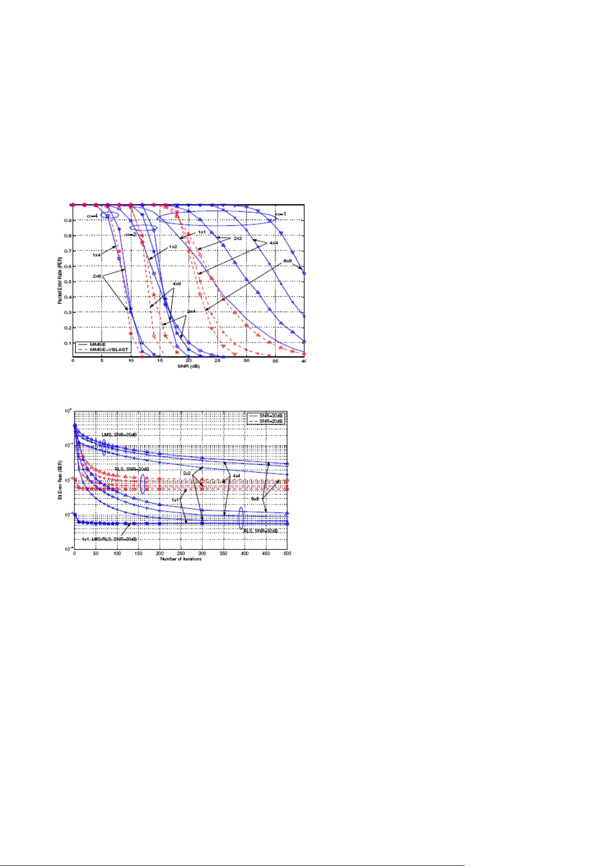
JOURNAL OF CO MPUTER SCIENCE AND ENGINE ERING, V OLUME 1, ISS UE 1, MAY 2 010 91 © 2010 JCSE http://sites.goo gle.com/site/jcs euk/ M I M O D e t e c t i o n A l g o r i t h m s f or H i g h D at a R a t e W i r e l e s s T r a n s m i s s i on Ni r m a l en d u B ik a s S in h a, R . Be r a a nd M . M it r a Abstract — Motivated by MIMO broad-band fading c hannel model, in this section a comparative study is presented regarding variou s uncoded adaptive and non-adaptive MIMO detection algorithm s with respect to BER/PER performance, and hardware complexity. All the s imulations are conducted within MIMO-OFDM framework and with a packet structure s imilar to that o f IEEE 802.11a/g standard. As the compari son results show , the RLS algo rithm appears to be an affordable solution for wide band MIMO syste m targeting at Giga-bit wireless transmission. So MIMO can overcome huge proces sing power required for MIMO detection b y using optimizing channel coding an d MIMO de tection . Index Terms — M IMO, OFDM ,U CLPA,SIC —————————— —————————— 1. INTRODUCTION In recent years, multiple input - multiple output (MIMO) based wireless communications has receive d widespread attention in the communication commu nity. To date, a majority of the work i n this are a has been of a theoretical nature [1], [2], [3] and little a ttention has been paid to the im plementat ion requirements of MIMO systems. Recently the UCLA Wireless Integrated Research (WIS R) gro up em barked on a project to d evelop a wideband ( 25MHz) real- time MIM O-OFDM test bed at 5.2GHz RF. The ultimate objective is to develop both system solution a nd novel VLSI architecture to enable real-time Gi gabps indoor wireless c ommunicati ons. One of the cha llenges in building a wideband MIMO system is the tremendous proce ssing power re quired at the receiver side. While coded MIMO schemes offer better performance than separate channel coding and modulation scheme by f ully exploring the trade-off between multip lexing and diver sity [4], its hardware complexity can be practically formidable, espe cially for wideband syste m with m ore than 4 antennas on b oth transmitter and re ceiver sides. On the ot her hand, it’s much ea sier to find a VLS I solution usi ng tra ditional channel coding schemes such a s convolution c ode and Turbo code f or data rate of hundreds of Mbps. For this reason, we start off by considering the uncoded M IMO schemes, also called spatia l multiplexi ng a s shown in Fig. 1, and carr y out a si de - by -side compara tive study to evaluate a n umber of uncoded MIMO detectio n algorithms from both performance and implementat ion point of view. —————————— —————— Prof. Nirmalendu Bikas Sinha, correspondin g author is with the Department of ECE an d EIE , College of Engineerin g & Management, Kolaghat, K.T.P.P Township, Purba- Medinipur, 721171, W.B., Indi a. Dr. R. Bera is with the S.M.I.T, SikkimManipal University, Majitar, Rangpo, East Sikkim, 737132 . Dr. M.Mitra is W ith t he Ben gal Engineering and sc ience University, Shibpur, Howrah, India . JOURNAL OF CO MPUTER SCIENCE AND ENGINE ERING, V OLUME 1, ISS UE 1, MAY 2 010 92 © 2010 JCSE http://sites.goo gle.com/site/jcs euk/ Fig. 1, Block diagra m of spati al multiplexing system . 2. MIMO DETECTION FOR FLAT- FADING CHANN EL A ) MIMO Channel Mod el MIMO syste ms are an extension o f smart antennas systems. Traditional smart antenna systems emp loy multiple antennas a t the r eceiver, whereas in a general MIMO system multiple antennas are e mployed both at the transmitter and t he rec eiver. The ad dition of m ultiple antennas at the transmit ter combined with advanced signal pr ocessing algorithms at the tra nsmitter and the receiver yields significant adva ntage over traditi onal smart ante nna sy stems - both in terms of capacity and diversity a dvantage. A MIMO channel is a wireless link between M tra nsmits a nd N receive antennas. It c onsists of MN elements that repr esent the MIMO chan nel coefficients. T he multiple transmit and receive antennas could belong to a si ngle user modem or i t co uld be distributed among diff erent users. The later c onfiguration is called distributed MIMO and cooper ative communications. Sta tistical MIM O channel models offer flexibility in selecting the channel pa rameters, temporal and spatia l c orrelations. MIMO channel si mulation tools are implemented based on these models. Several statistical MIMO channel models were proposed in [5] and [6 ].Both model s intro duced spatial correlation by multiplying a matrix of u ncorrelated random varia bles by a square root of a covariance matrix and b oth are based o n similar assumptions. However, they differ in their approach. In [7 ], the authors vali date t he statistica l model of [5] based on mea surements in microcells and microcells. They showed t hat the eigen value di stribution of the m odel matches the measureme nts. F ig.2 (a) , (b), ( c) and (d) shows conceptual diagram of existing technology, smart antenna system and MIMO channels respectively. a M a 2 SCATTERR ING MEDIUM 1 2 Channel Decoding a 1 N 2 M 1 Channel encoding T X DATA R X DATA JOURNAL OF CO MPUTER SCIENCE AND ENGINE ERING, V OLUME 1, ISS UE 1, MAY 2 010 93 © 2010 JCSE http://sites.goo gle.com/site/jcs euk/ Fig. 2 (a ) Existing technology, (b) & (c) Smart antenna system Fig. 1(d) A MIMO wireless channel 3. P erformance Analysis of di fferent MIMO detectors A straightforward approach to recover x from y is to use an M X N weig ht mat rix W to linearly c ombine the elements of y to es timate x, i.e. . 3.1 Maximum Li kelihood (ML): The ML receiver performs optimum vector decoding and is optimal in the sense of minimizing t he error probability. ML receiver is a method that c ompares the received signals with a ll possible transmitted signal vector which is modified by channel matrix H and estimates trans mit symbol ve ctor x accordi ng to the Maximum Likelihood pri nciple , whic h is shown as: ….(1) Where the minimization is performed over all possible transmit estimated vector symbols . A lthough ML detection offers optimal error performance, it suffers from complexity issues. It has exponen tial com plexity i n the sense that the receiver has to consider |A| M possible symbols for an M tra nsmitter a ntenna system with A i s the modulation conste llation. SISO SIMO N R MISO M T M Scatterers T X 1 2 N R X 1 2 JOURNAL OF CO MPUTER SCIENCE AND ENGINE ERING, V OLUME 1, ISS UE 1, MAY 2 010 94 © 2010 JCSE http://sites.goo gle.com/site/jcs euk/ 3.2 V -BLAST Zero Forcing (ZF) characteristic: We ca n reduce the decoding co mplexity of the ML receiver significantly by employing linear receiver front - ends to separate the trans mitted data streams, and then independently decode each of the streams. Simple linear receiver with low computational complexity and suffer s from noise enhancement. It works best with high SNR. The solution of the ZF i s given by: Where, represents the pseudo -inverse. The ZF receiver converts the joi nt d ecoding problem into M single stream decoding pr oblems thereby significa ntly reducing rece iver complex ity. This c omplexity reducti on comes, however, at the expense of noise enhance ment which in ge neral results in a significant performa nce degradation (compare d to t he ML decoder). The divers ity order achieved by each of the individual data streams equals N - M + 1. 3 .3 . V-BLAST with Minimum Mean Square E rror (MMSE): The MMSE receiver suppre sses both the interference and noise compone nts, whereas the ZF receiver removes only the interference comp onents. This implies that t he mean square error between the transmitted symbols and the estimate of the receiver is minimized . Hence, MM SE is superior to ZF in the pr esence of noise. S ome of t he important characteristics o f MMSE d etector are simple linear re ceiver, superior p erformance to ZF and a t Low SNR, MMSE bec omes matched filter. A lso at high S NR, MMSE becomes Zero- Forcing. MM SE receiver give s a solution of: At low SNR, MMS E becomes ZF: At high SNR, MMS E becomes ZF: i.e., the MMS E receiver approaches the ZF rece iver and therefore realizes ( N-M + 1 ) th order diversity for each data stream. 3 .4 .V -BLAST with Maxi mal Ratio Co mbining (MRC) : MRC combines the information from all the received branches in order to maximize the ratio of signal to noise power, which gives it its name. MRC works b y weighti ng each branch with a compl ex factor and then adding up the branches, MRC is intuitively a ppea ling: the t otal SNR is achieved by si mply adding up the branch SN Rs when the appropriate weight ing coefficients are used. BER for MRC in Raylei gh fa ding channel (1 x2) with BPSK modulation, 3 .5 . STBC (space-time b lock codes): STBC is a class of linear coding for MIMO systems that aims to maximize the syst em d iversity gai n ra ther than the data ra te. A very popular STBC for a two transmit antennas setup was developed by Alamouti, whi ch is illustrated in Fig.3 . It is de signed for 2x2 MIMO syst ems and its simplicity and high frequency have led to its wide adoption in MIMO syste ms. In t his scheme o rthog onal signals are transmitted f rom each a ntenna, whic h greatly simplifies receiver desi gn. This particular scheme is restricted to using M = 2 antennas at the tra nsmitter but can any nu mber of re ceive antennas N .Two QAM symbols S 1 and S 2 for transmission by the A lamouti sche me are encoded in both the space and time domain at t he two tra nsmitter antennas over the co nsecutive sy mbol periods as s hown in equati on( 2 0). The informatio n bits are first modulated using a modulation scheme (for exa mple QPSK). The encoder then ta kes a block of two modulated symbol s s 1 JOURNAL OF CO MPUTER SCIENCE AND ENGINE ERING, V OLUME 1, ISS UE 1, MAY 2 010 95 © 2010 JCSE http://sites.goo gle.com/site/jcs euk/ and s 2 in each encodi ng op eration a nd gives to the transmit antennas a ccording to the code matrix, The code matrix has t he following property Where is the 2x2 identity matrix. In the above matr ix the f irst colum n represents the first trans mission pe riods and the sec ond co lumn, the second tra nsmission period . The first row c orresponds to the symbols transmitted from the first antenna and second row corresponds to the symbols transmitted from the second antenna. It mea ns that during the symbol period, the first a ntenna tr ansmits s 1 and sec ond ante nna s 2 . During the second symbol period, the first antenna transmits – s 2 * and the second a ntenna trans mits s 1 * being the complex c onjugate of s 1 . Thi s i mplies that we are transmitting b oth in spac e (a cross two a ntennas) a nd time (two transmission intervals). This is space time coding. Hence, S 1 = [s 1 -s 2 * ] and S 2 = [s 2 s 1 * ] Moreover a close look reveals that sequences are orthogonal over a fra me interval, since the inner product of the sequences S 1 and S 2 is zero, i.e. S 1 .S 2 = s 1 s 2 * - s 2 * s 1 =0 ……….. ( 10 ) In a f ast fading channel, the BE R is of primary interes t since the channel varie s e very sy mbol ti me; while in a slow f ading situation, the FER (Frequency error rate) is more important because c hannel stays the same for a frame. 3. 6. Linear Adaptive MI MO Detection Instead of assuming known channel matrix H , which usually requires cha nnel probing before e ach transmission and then ca lculating W in a bur sty man ner, adaptive algorithms esti mate W directly through iteration via the use of a known training sequence a t the beginning of each tra nsmission. A) Least Mean-Squ are (L MS): LMS is an estimate of the steepest descent a lgorithm [5] and upda tes W according to Where is the update step si ze .For LMS to to converge in the mean-squared sense, i.e, needs to satisfy . Where i s the l argest ei gen value of . Therefore, the convergence of LMS depends on both channel condi tion and si gnal to noise ratio at the input o f the receiver . The final residual error also depends on the value of μ. B) Recursive Least -Squares (RL S): RLS is the recur sive solution to the exp onentially weighted least - squares ( LS) problem [5]. The recursive optimal solution at time instant i is is the exponential forgetting facto r , and is the inverse of the weigh ted correlation matrix of y i with initial condit ion The scalar is usually a large pos itive number and λ i s very close to 1. Compared to the sto chastic estimation problems given previ ously w hich require the signal statistics such as correla tion ma trix, LS problem is deterministic [8 ], [9 ]. Therefore, RLS ca n be used to find the LS solution to a non- stationary process, or s imply said, RLS can track nonstationary process i n the L S sense. When x i , H , a nd v i are all stationary, it is the weighted time-average esti mate to MMSE as i → ∞ if Rxy a nd Ry are replaced by and respectively. JOURNAL OF CO MPUTER SCIENCE AND ENGINE ERING, V OLUME 1, ISS UE 1, MAY 2 010 96 © 2010 JCSE http://sites.goo gle.com/site/jcs euk/ Fig .3 , Perf ormance curv es for different linear detectors (ML, STBC, ZF, MMSE, and MRC) in 2×2 MIMO - V- BLAST system in a slow fa ding channel. Fig. 3 shows all the simulation results. A t a certain B it Error Rate point, BE R=0.0 01, there is a pproximately 2.3dB SNR difference between the V -BLAST S IC system with ZF detectors a nd the V -BLA ST SIC ordering syst em. The diff erence is smaller than what we expected. The performance curves of th ese two systems are close to each other, especially whe n the SNR is low, but the gap gets larger when the SN R gets higher. When the SN R is low, which means the noise is large, the po st detection SNR is mainly affected by the noise, thus we will n ot see a big differ ence between the SIC system with or without ordering. When t he S NR gets higher, the post detection SNR is mainl y a ffected by the channel matrix H. The post detection SNR of a stream will be of great d ifference when the stream is suffering from a deep fading, it is sensitive to the channel characteristic. If there are more antennas in t he tra nsmitter , which means there are more stages, or t he cha nnel cond ition is more c omplicated, we will observe more improvement from using the orderi ng strategy. If we u se a MRC detector instead of a ZF detector at the first stage of the V-BLAST SIC order ing system, we will have a gain of 12 .3dB; this gain comes from the joint ML detector. When the BER is equal to 0.001, we need SNR=3dB in the genera l V -BLAST sys tem with the ML detector, a nd we need SNR=4.6dB in the S IC ordering system w ith the ML detector a t the first stage. That is a difference of only 1.6dB, thus we can use the S IC ordering system with first stage ML instead of the general V-BLA ST scheme since these two sche mes perform simi larly, a nd we do not need to code across the transmitting antennas. C ) PER Performance The PE R perfor mance curv es are shown i n F ig. 4. ZF and MMSE yield very close PER perf ormance, and similarly, ZFVBLAST and M MSE -VBLAST (except for M = N > 1 ). For th is re ason, the curves in Fi g. 4 on ly il lustrate MM SE and MMSE-VB LAST. The performance of VBLAST is consistently better t han ZF/MM SE since for PER to re ach below 10 0%, the SNR is already sufficiently high for infrequent error pr opagation. At α = 1, the PE R for MM SE increases with the nu mber of antennas as compare d to the roughly overlapped cur ves previously observed in the BER plo t. For τ rms = 5 0ns, the channel selectivity le ads to a d egradation in PE R c ompared to flat -f ading cha nnel. This is because for each packet, it’s more likely to see bit errors caused by a deep null in the cha nnel frequency response (correspondin g to lower S NR), than i n channels with smaller τ rms . This is rea dily mit igated via interlea ved channel coding techniques. On the other ha nd, the B ER stays the same for differ ent τ rms as long as the cyclic pref ix is suff iciently long compared to τ rms . In our simulatio ns, we have used a cyclic prefix length of 1 6 × 4 0ns= 640ns, long enough for τ rms = 50ns. D) Convergence of LMS/RL S LMS and RLS a re resursive alternatives to the ma trix inversion-based solutions. Under the simulation environments, the BE R/PER perf ormance of RLS will ultimately converge to the M MSE results shown before with sufficient trai ning while that of LMS should get very close when μ is very small. What’s key here is t he convergence speed, as shown in Fig. 5 in the form of ensemble average BER learnin g curves. As expected, at the same SNR, LMS converges much slower than RLS except for 1 × 1 case where the lea rning curve s actu ally overlap with each other. The re quired training length depends on va rious factors including number of antennas, SN R, and upd ating fa cto r μ or λ . F or RLS, the training lengt h is roug hly o n the ord er of M · N . For LMS, it’s about 10 times longer. At higher SN R, it takes RLS longer to converge becaus e the lea rning curve at higher SNR has a deeper BER floor to reach while the initial (also fastest) learning slope for different S NR is similar. Larger μ or smaller λ can increase the speed of convergence for LMS and RLS, respectively. But on the 0 2 4 6 8 10 12 14 16 18 10 -4 10 -3 10 -2 10 -1 10 0 Eb/ No , d B Bit E rror Rat e BER for QPSK m odul ation with ML,STBC,ZF, MMSE & MRC det ector for 2 X 2 (Rayleig h chan nel) ML STBC ZF MMSE MRC JOURNAL OF CO MPUTER SCIENCE AND ENGINE ERING, V OLUME 1, ISS UE 1, MAY 2 010 97 © 2010 JCSE http://sites.goo gle.com/site/jcs euk/ other hand, they tend t o adve rsely a ffect the fi nal convergence perf ormance at the same time. The convergence of LMS also d epends on the channel condition number (eigenvalue spread) . RLS guarantees the convergence at the price of higher hardware complexity and les s robus tness t o quantizatio n effec ts [8], [9 ]. Similar to the BER perf ormance, the effect of c hannel delay spread on the converge nce of LMS /RLS is negligible when the cycl ic prefix is long enoug h. Fig. 4. PER performance of MMS E and MMSE - VBLAST Fig. 5 . The learning cur ves of L MS ( μ = 0 . 02) and RLS ( λ = 0 . 99) CONCLUSION In this paper , we ha ve pro vided an ov erview of va rious M IMO detection algo rithms fo r spatial multipl exing systems. The si mulated perfo rmance of these algorithms i s co mpared, and t his co mparison is further extended to a first ord er estimatio n of their hardware co sts. From these comparisons, it is observed that VBLAS T ge nerally outperfo rms ZF/M MSE, at the cost of si gnificantly higher i mplementatio n complexity . In fact, ZF -VBLAST is only slightly better than M MSE (2 ∼ 3dB at uncoded BER of 10 − 3) . The adva ntages of VB LAST over ZF/MMSE become much l ess signif icant when α > 1 because of the antenna div ersity gain. MMSE -VBLAS T performs much better t han ZF- VBLAST . However , i n practice, i naccurate estimates as w ell a s the channel matrix itself tend to reduc e this gain. The study shows that RLS has a much lo wer computation i ntensity t han ZF/MMSE/VBLA ST and achieves the performance of MMSE with suffi cient traini ng. Thi s is done by spread ing out the co mputatio n through multi ple iterations. RLS i s superior to LMS i n terms of conv er gence speed, and its hardwa re cost is o n the sa me order as LMS. Co mpared to ZF/MMSE/VBLA ST , RLS doesn’ t requi re explicit channel information and subseque nt matri x inversion, and ca n be implemented using the QR -decompo sition based syst olic array architecture [8] [9]. Theref ore, it can be concl uded that RLS presents t he best perf ormance to co mplexity metric among the surveyed algo rithms for Giga-bps MIMO wireless systems. Based on these findings, RLS has been c hosen for the MIMO detec tion in the UCLA MIMO-OFDM test bed [10], [11 ]. REFERENCES [1] G. J. Foschini and M. J. Gans, “On limi ts o f wireless cmmunications i n a fading environment wh en using multipl e an tennas,” Wireless Personal Communications , vol. 6, pp. 311 – 335 , March 1998. [2] G. J. Foschini, “Lay ered space -time architecture for wireless co mmunications in a fadi ng enviro nment using multi- element antennas,” Bell Labs T ech. J., vol. 1, no . 2, pp. 41 – 59, Autumn 1996. [3] P . W . W ol niansky , G. J. Foschini, G. D. Golden, and R. A. V alenzuel a, “V -BLA ST : A n architecture for realizing very high data rates over the ri ch-scatteri ng wi reless channel,” in Proc. ISSSE - 98 , Italy , Sep. 1998 . [4] L. Zheng and D. T se, “Diversity and multiplexing: a fundamental tradeoff i n multipl e antenn a channels,” IEEE T ran. Inform. Th., vol. 49, pp. 1073 – 96, May 20 03. [5 ] J. Fuhl, A. F . Molisch, and E. Bonek, “Unified channel model for mobil e radio systems with smart anten nas,” in Proc. Inst. Elec t. Eng., vol. 145,Feb. 1998, pp. 32 – 41. [6 ] G. G. Rale igh and J. M. Cioffi, “Spatio -temporal JOURNAL OF CO MPUTER SCIENCE AND ENGINE ERING, V OLUME 1, ISS UE 1, MAY 2 010 98 © 2010 JCSE http://sites.goo gle.com/site/jcs euk/ coding fo r wireless communication,” IEEE T rans. Commun., vol. 46, pp. 357 – 366 , Mar .1998. [7 ] G. G. Raleigh and V . K. J ones, “ Multiva riate modulation and coding for wireless communication,” IEEE J. Select. Areas Commun., vol. 17, pp.8 51 – 866 , 1999. [8] S. Haykin, Adaptiv e Fi lter Theory , 3rd ed. Prentice - Hall, 1996. [9] A. Sayed, Fundamentals of Adaptive Fil tering. Wiley - IEEE Press, 200 3. [10] R. Rao and et.Al., “Multi -antenna testbeds f or research and education in wirel ess communications,” IEEE Commun. Mag., vol. 42, no. 12, pp. S41 – 5 0, December 2004 . [11] S. Lang, R. Rao, and B. Daneshrad, “De sign and development of a 5.25 GHz software defined wireless OFDM communi cation platfo rm,” IEEE Co mmun. M ag., vol. 42, no. 6, pp. S6 – 12, June 20 04. Prof. Nirmale ndu Bikas Sinha received the B. Sc (Honours in Physics), B. T ec h, M. T ech degrees i n Radio -Physics and Elec tronics from Calcutta University , Calcutta,India,in19 96,1999 and 2 001, respectively . He i s currently working towa rds the Ph.D degree in Electronics and T elec ommunic ation Engineeri ng at BESU. Since 2003, he has b een associated with the Coll ege of Engineeri ng and Management, Kolaghat. W .B , I ndia where he is cur rently an Asst.Professor is with the department of Electronics & Communicatio n Engineering & Electronics & Instrumentation Engineeri ng. Hi s current research Interests are in the area of signal processing for high- speed digital communicatio ns, signal detection, MIMO, multiuser commu nications,M icrowav e /Millimeter wav e based Bro adband Wireless M obile Communicati on ,semiconductor Devices, Remote Sensing, Digi tal Radar , RCS Imaging, and W irel ess 4 G communication. He has published large numbe r o f papers in different international Conference, p roceedings and journals. He is presently the editor and reviewers in different international jo urnals. E-mail: nbsinha@yahoo.co.in Dr . Rabindranath Bera is a pr ofessor and Dean (R&D), HOD in Sikkim Manipal University a nd E x- reader of Calcutta Uni versity , Indi a. B.T ech , M.T ech and Ph.D.degre es from Institute of R adio- Physics and Electro nics, Calcutta University . Hi s research areas are in the field of Digital Radar , RCS Imaging, Wireless 4G Communications, Radiometri c remo te sensing. He has pu blished large number of papers in different national and intern ational Conference and journals. Dr . Monojit Mitra is an Assistant Professor i n the Department of Electronics & T el ecommunicatio n Engineeri ng of Bengal Engineering & Science University , S hibpur . He obtained his B.T ech, M.T ech & Ph. D .degrees from Calcutta U niversity . His research areas are in the f ield of Mi crowa ve & Microelec tronics, especially in the fabrication of high frequency soli d state device s li ke IMP A TT . He has published large number of papers in different national and international journals. He has handled spo nsored re search pro jects of DOE and DRDO. He is a member of IE TE (I) and Institution of E ngineers (I) society .
Original Paper
Loading high-quality paper...
Comments & Academic Discussion
Loading comments...
Leave a Comment