This paper aims to implement the six channel redundancy to achieve fault tolerance in testing of satellites with acoustic spectrum. We mainly focus here on achieving fault tolerance. An immediate application is the microphone data acquisition and to do analysis at the Acoustic Test Facility (ATF) centre, National Aerospace Laboratories. It has an 1100 cubic meter reverberation chamber in which a maximum sound pressure level of 157 dB is generated. The six channel Redundancy software with fault tolerant operation is devised and developed. The data are applied to program written in C language. The program is run using the Code Composer Studio by accepting the inputs. This is tested with the TMS 320C 6727 DSP, Pro Audio Development Kit (PADK).
Deep Dive into Implementation of the Six Channel Redundancy to achieve fault tolerance in testing of satellites.
This paper aims to implement the six channel redundancy to achieve fault tolerance in testing of satellites with acoustic spectrum. We mainly focus here on achieving fault tolerance. An immediate application is the microphone data acquisition and to do analysis at the Acoustic Test Facility (ATF) centre, National Aerospace Laboratories. It has an 1100 cubic meter reverberation chamber in which a maximum sound pressure level of 157 dB is generated. The six channel Redundancy software with fault tolerant operation is devised and developed. The data are applied to program written in C language. The program is run using the Code Composer Studio by accepting the inputs. This is tested with the TMS 320C 6727 DSP, Pro Audio Development Kit (PADK).
Acoustic Test Facility is a national facility for acoustic environmental qualification of satellites, launch vehicle stages and their subsystems for the ISRO [1]. The ATF has a reverberation chamber (RC) for simulating the acoustic environment experienced by spacecraft and launch vehicles during launch [2]. The RC has a diffused uniform sound pressure level distribution. Its wall surface ensures reflectance of 99% of the sound energy. It is used for simulating the acoustic environment experienced by spacecraft and launch vehicles during the launch. The one such facility is shown in Fig. 1.
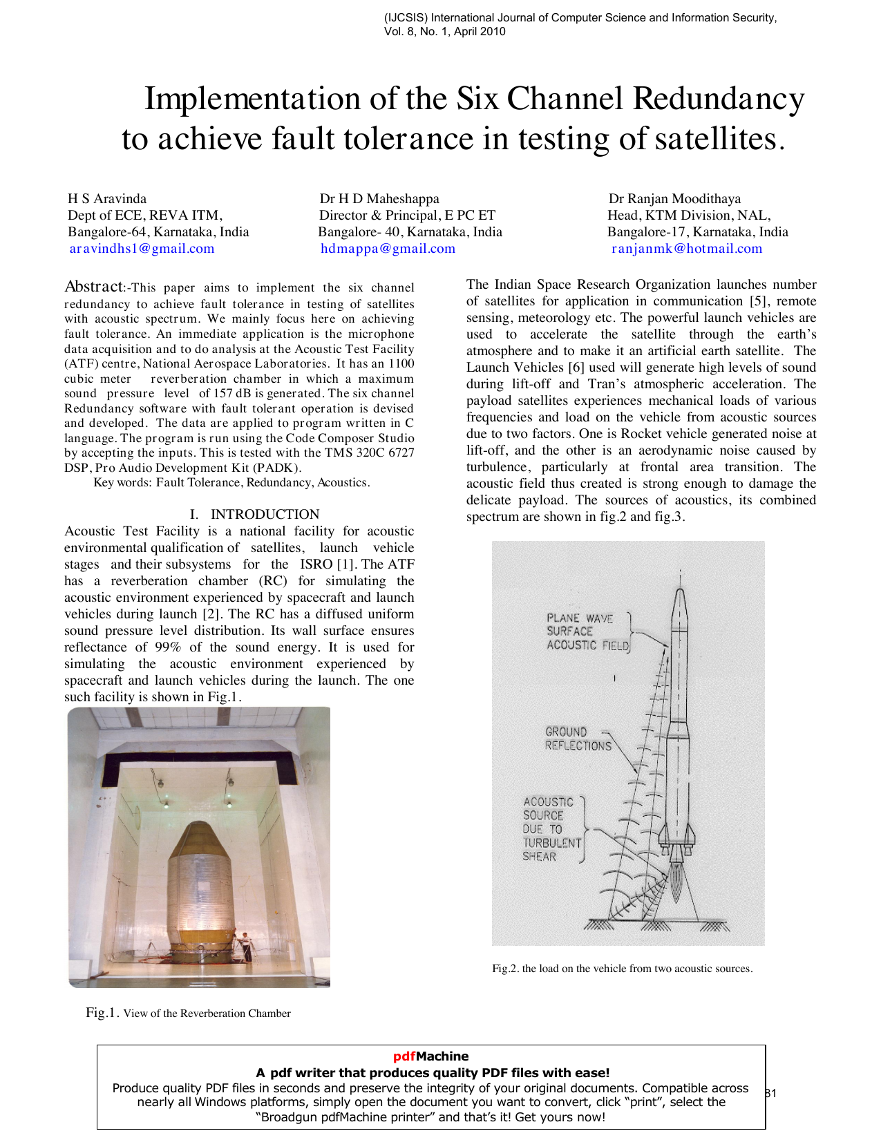
The Indian Space Research Organization launches number of satellites for application in communication [5], remote sensing, meteorology etc. The powerful launch vehicles are used to accelerate the satellite through the earth’s atmosphere and to make it an artificial earth satellite. The Launch Vehicles [6] used will generate high levels of sound during lift-off and Tran’s atmospheric acceleration. The payload satellites experiences mechanical loads of various frequencies and load on the vehicle from acoustic sources due to two factors. One is Rocket vehicle generated noise at lift-off, and the other is an aerodynamic noise caused by turbulence, particularly at frontal area transition. The acoustic field thus created is strong enough to damage the delicate payload. The sources of acoustics, its combined spectrum are shown in fig. 2 and fig. 3.
The acoustic environment inside the Reverberation Chamber is created by modulating a stream of clean and dry air at about 30 PSI pressure using electro pneumatic transducers. The drive signal is derived from a random noise generator and modified by a spectrum shaper. The microphone data from the RC is observed on a real time analyzer and the spectrum shaper outputs are adjusted to achieve the target spectrum. There are two sets of modulators, one delivering an acoustic power of 60KW in the 31.5 Hz to 500 Hz and the others delivering 20 KW in the 200 to 1200 Hz range, the spectrum beyond 1200 HZ is controlled to some extent using the effects of the higher harmonics by changing the spectral contents of the drive to the modulators. The acoustic excitation is coupled to the RC through optimally configured exponential horns to achieve efficient transfer of the acoustic energy into the chamber. The chamber wall surface treatment design ensures reflectance of 99% of the sound energy incident on them. The chamber has a diffused uniform, sound pressure level distribution with in 1dB in the central ten percent of volume of the chamber where the test specimen is located. The spectrum for almost all contemporary launch vehicles around the world can be The satellite is kept in RC and the high frequency high level spectrum characteristics of the launch vehicle are generated and its dynamic behavior is studied. It is essential that the acoustic noise generated is a true simulation of the launch vehicle acoustic spectrum, and it is the input acoustic load to be simulated in the RC and is specified as SPL (sound pressure level) in dB verses frequency. The spectrum of various launch vehicles like delta, atlas centaur, titan-IIIC, Arianne, vostok, ASLV, PSLV, GSLV.., and Indian satellites like IRS, INSAT.., are realizable in the Reverberation Chamber. Each launch vehicle has unique spectral features and is drawn in Octave Band Centre Frequencies (OBCF), in the range from 31.5 Hz to 16 kHz. pdfMachine A pdf writer that produces quality PDF files with ease! Produce quality PDF files in seconds and preserve the integrity of your original documents. Compatible across nearly all Windows platforms, simply open the document you want to convert, click “print”, select the “Broadgun pdfMachine printer” and that’s it! Get yours now!
The Three levels of acceptance of acoustic spectrum are , first is Full level or Qualification test, it is normally for 120 seconds and Maximum of 156dB, second is Acceptance level test, it is normally for 60 or 90 seconds and Maximum of 153dB, third is a Low level test, it is normally for 30 seconds and Maximum of 150dB.
Fault tolerant application software to ensure data integrity will be developed. This paper is implemented by taking the six channel data from reverberation chamber and is applied as the input to the program. The six microphones data are connected to the TMS 320C 6727 DSP, Pro Audio Development Kit (PADK) after signal conditioning via analog to digital converters. All six microphone data is fed to DSP processor as shown in Fig. 5. The FFT is taken for all the six channel data and are compared with each other to find out which channel microphone data is good or bad. A threshold level is maintained to check the validity of the microphone. If the data is well with in the threshold it is accepted or else it will be rejected. Here if the two channel microphone data is bad then it will only be identified.
The data is extracted using the six microphone channels. It is
…(Full text truncated)…
This content is AI-processed based on ArXiv data.