Physical layer network coding with multiple antennas
The two-phase MIMO NC (network coding) scheme can be used to boost the throughput in a two-way relay channel in which nodes are equipped with multiple antennas. The obvious strategy is for the relay node to extract the individual packets from the two…
Authors: Shengli Zhang, Soung-Chang Liew
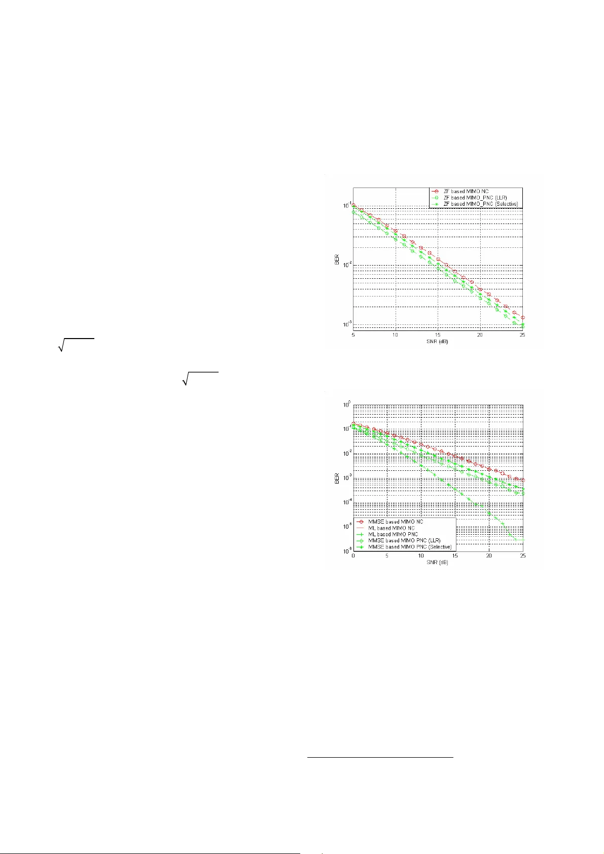
Physical Lay er Network Coding with M ultiple Antenna s Shengli Zhang †‡ Soung C hang Liew † † Department of Information Engineering, the Chinese University of Hong Kong, Hon g Kong ‡ Department of Communication Engineering, Shenzhen University , Chin a. {slzhang, soung}@ie.cuhk.edu.hk Abstract: The t wo-phase MIM O NC (network coding) scheme can be used to boost the throughput in a two-way rela y ch annel in which nodes are equipp ed with multiple antenn as. The obvious strategy is for the rela y node t o extract the i ndividual packets from th e two end nodes and mix the two packets to form a n etwork-coded packet. In this paper, we propose a new scheme called MIMO PNC (physical network coding), in which the relay ex tracts the summation and diff erence of the tw o end packets and the n c onverts them to the network-coded form. MIMO PNC is a natural com bination of the single-antenna PNC scheme and the li near M IMO detection scheme. The ad vantages of MIMO P NC are many . F irst, it removes the stringent carrier-phase requirement in single-antenna PNC. S econd, it is linear in complexity with resp ect to the constellation size and the number of simultaneous d ata stream s in MIMO. Simulation show s that MIMO PNC outperforms the straightforward MIMO NC significantly under random Ra yleigh fading chann el. Based on our analysis, we further conjecture that MIMO P NC outperforms MIM O NC under all possible realizations of the channel. I. INTRODUCION In wireless networks, the use of relay has many advantages. It c an lead to better co verage and connectivity . W ith a smaller distance for node -to-node transmi ssions, the power c onsumption can be r educed. At th e sa me time, the detrimental effects of the interference s fro m other transmissions can be alleviate d, leading to higher capac ity p er unit area. Consider the si mple two -way r elay cha nnel ( TWRC) shown in Fig. 1 . In [1 ], the authors introduced network co ding into T WRC: the two end nod es tra nsmit their packets to the relay in two different ti me slots; the relay then forms a network-coded p acket out of the two p ackets and broadcast it to the end nodes. The num ber of ti me slots needed to exchange one packet is 3. Subsequent to [ 1], w e prop osed physical la yer net work coding (PNC) [2]. P NC allo ws the t wo end nod es to trans mit their packets i n the same time slot. The superimposed packets received simultaneously are then directly trans formed to a network-coded packet at the physical layer of t he relay . As a result, the number of time slots needed to exchange one packet is reduced to 2. PNC is attra cting increasing attentio n. At the communication level, variants of P NC have been p roposed [3, 4, 5] to i mprove p erformance o r to ea se i mplementation. At the net work le vel, P NC has also been shown to be able to increase network capac ity b y a fixed factor [6 , 7]. In ad dition, information-theor etic studies indicate that PNC can allow the capacit y of T WRC to be approached in both low SNR a nd high SNR regio ns [8, 9 , 10 ]. T o d ate, most work o n PNC a ssumes si ngle antenna at the wireless devices. Si nce multiple-inp ut-multiple-ou tput (MIMO) can incre ase t he c hannel capacity , and multiple antennas ha ve been w idely eq uipped in most modern wirele ss devices, the co mbination of PNC with MIMO will be o f great interest. T o the authors’ kno wledge, little work ha s bee n done on this front. Refs. [11, 12] explored this combinatio n, assuming the availability o f full channel sta te infor mation (C SI) at t he two transmitting nodes ( end nodes) . The end nodes explo it the CSI to pre-cod e the packet before transmission. The p re-coding essentially multiplie s the i nverse of the channel m atrix to the MIMO inputs b efore transmission. T his cancel s o ut the effect of the MIMO channel. This p re-equalization, however, requires the packet s of the two end nodes to be s ynchronized (including carrier-phase s ynchronizatio n) when t hey arri ve at the r elay . T his i mposes a significa nt i mplementation difficulty . The maximum likelihood (ML) b ased d etection and encoding schemes in [5 ] can also be extended to the MI MO ca se without the need for c arrier phase s ynchronization. Howev er , the complexity increases exp onentially with the constellatio n size and the number of data streams transmitt ed simultaneousl y from the end n odes. In this p aper, we propose a new MIMO PNC sc heme in which the relay extracts the summation and difference of the t wo end packets and then converts them to the network-c oded form. Our scheme only req uires CSI only a t t he r eceiver . It can be regarded as a natural exte nsion of the si ngle-antenna P NC [ 2], and its advantage s are also similar . A significant implication, however , is t hat unli ke t he si ngle-antenna PNC, our MIM O PNC sche me gets r id o f the r equirement for carrier- phase synchronization, br inging im plementation clo ser to reality . Also significant is the fact that instead of the exponential complexity in [5], our schem e, which m akes use of linear MIMO detec tion methods, is l inear in complexit y . For compariso n purposes, thi s p aper also considers the two-phase MIMO N C scheme in which MIMO tech nique is used to extract the individ ual p ackets fro m the two end nodes before co nverting them into a net work-coded packet (a s oppo sed to our MIMO_PNC in which the o verlapped packets from the t wo end nodes ar e directly converted into a network-coded p acket wi thout extracting the individ ual packets). A nalysis a nd si mulation resu lts sho w that MIMO PNC can achieve much better BER p erformance than MIM O NC. The rest o f thi s pa per is organized as follo ws. Section II defines the syste m model and illustrates the basic idea of MIMO PNC with an e xample. Sectio n I II presents the d etails MIMO PNC, assuming two antennas at t he relay and one antenna at t he end nod es. The BER per formance is analyze d. Section IV provides numerical si mulation results that demonstrate the super iority of MIMO P NC over other schemes. T his is follo wed by a discu ssion of the ge neral MIMO P NC setting in whic h the two end nod es are also equipped with mu ltiple antennas. Section V conclu des this paper . II. SYST EM MODE L AND ILL USTRA TING EXAMPLE 1 N 2 N 3 N Figure 1. T wo way rela y channel A. Syste m Mo del: This p aper considers the two -way relay channel as shown in Fig. 1. T he two end nod es, N 1 and N 2 , exc hange information through the relay node N 3 . T here is no direct l ink between the t wo end nodes. Fo r simplicity , we assu me the end nodes are equipped w ith sin gle antenna and the r elay node is equipped with two antennas. The P NC tra nsmission co nsists of two phase. In the first phase, both end nodes tr ansmit to the relay node simultaneousl y . Here, we as sume t he two end nod es’ sig nals arrive a t the r elay nod e at a symbol level s ynchronization. Then, the received signal at the relay node can be expressed as: 1 11 1 12 2 1 2 21 1 22 2 2 r h x h x n r h x h x n = + + = + + (1) where r i denotes the received baseband signal at t he i -th antenna of the relay node, h i,j is the co mplex Gaussian channel co efficient fro m nod e N j to t he i -th anten na of the relay node, x i is the transmit ted baseband signal of node N i , and n j is the Co mplex Gaussian noi se at the j -th antenna o f the relay nod e with zero mean and variance 2 σ for both dimensions. BPSK modulatio n is assumed at bo th nodes ( all the schemes presented in this paper can be easily extended to QPSK, and the main results al so hold for QP SK). In the first pha se, we assume full channel information at the rela y nod e ( receiver node) and no channel infor mation at the end nodes (tra nsmitter nod es). In particular, the effects of transmit po wer and carrier-phase difference are co mbined into the co mplex channel co efficients. Eq ( 1) can be re w rite i n the vector for m as R HX N = + (2) Throughout this paper, a capital letter, for example H , denotes a matrix or a vector and the co rresponding lower case letter, for example h i,j , denotes its element on i -th ro w a nd j -th column. The relay node then tries to estimate the n etwor k coded f orm of the two e nd nod es’ signals (i.e., 1 2 x x ⊕ in this paper). In the second phase, the r elay node broad casts the estimated net work-coded packet to bo th end nodes. Eac h end node then d ecodes its o wn target packet from the rece ived network-coded packet with self in formation. The second phase is t he same a s a traditional MI MO broad cast with standard network d ecoding [1 3]. This pa per focuses o n the first phase. B. Illustrating Example: For the first pha se, the tra nsmission in (2 ) can be regarded as a point-to -point 2-by-2 MIMO s ystem (a distributed MIMO system). The goal of the relay node is to obtain an estimate of 1 2 x x ⊕ . In a traditional MIMO NC scheme, the processing of the re lay node is to explicitly decode 1 x and 2 x before network-encod ing t hem in to 1 2 x x ⊕ . However, this scheme is subo ptimal si nce it d oes not make use of the fact that onl y 1 2 x x ⊕ rather than individual x 1 and x 2 i s need ed at the rela y nod e. W e no w pr esent an example to illustra te the sub optimality o f the MIMO NC processing. This example a lso reveals the advantages of our proposed scheme. Consider a special scenario i n satellite co mmunicatio n where the t wo end nodes are o n the eart h and t he relay nod e is the satellite. Suppo se it is a li ne-of-sight chan nel without any multipath and th e two end nodes’ signal arrive at the two antennas of the satellite i n a synchrono us way . Neverthele ss, the channel matrix co uld still be rea lized in many forms. F or example, it could be 1 1 1 1 H = . (3) In (3) , H is not a full-ra nk matrix and the relay can never obtain x 1 and x 2 individually fro m t he received signal vect or R . As a result, the multiple a ccess rate o f 1 2 x x ⊕ , based on the MIMO NC scheme, is zer o. W ith PNC, the goal of the re lay is to estimate 1 2 x x ⊕ from R without first esti mating x 1 and x 2 . In fact, the information on x 1 + x 2 , which can be obtained dire ctly fro m R by matrix multiplication, is a more useful in termediate step as far as the estimation o f 1 2 x x ⊕ is concerned . Based o n the above observation, we prop ose the following MIMO PNC sche me. W e now illu strate the basic idea based on the specific H in ( 3). The treatment for general H can be found in Sec tion III. With the H in (3), the rela y first combines the sig nals from the two receiving an tennas as 1 2 1 2 1 2 1 ( ) 2 2 n n r r r x x + = + = + + . (4) After that, the r elay maps r to 1 2 x x ⊕ according to the PNC mapping in [2]. As a result, i n this new sc heme, t he r elay can obtain 1 2 x x ⊕ with a lmost full rate [8-10 ]. T his example shows that the proposed scheme may outperfor m the MIM O NC scheme signi ficantly . In the following sections, we elaborate our proposed scheme, w hich makes use of li near MIMO detection. W e pr ove that it outperfor ms t he trad itional MIMO NC sc heme for all channel rea lizations o f H . III. MIMO PN C DETECTIO N SCHEME In this section, we present the de tails of o ur pro posed detection and e ncoding sc heme to o btain 1 2 x x ⊕ from the received signals, i nspired b y t he ba sic idea of PNC [ 2]. Before that, we first revie w the traditiona l t wo pha se re lay scheme based on li near MIMO detection approaches f or a purpose o f comparison, i.e., th e MIMO NC sc heme. A. Detect ion and Encoding Based on Linear MIMO Detection: As mentioned in the previous sectio n, the obj ective of the relay is to obtain t he XOR of the two end nodes information, i.e., 1 2 x x ⊕ . A major detection method in MIMO for spatial-multiplex ed systems is linear detectio n followed by q uantization (e.g., [2]). Let us first consid er the applicatio n of this method on the traditional MIMO N C sc heme in which x 1 a nd x 2 a re to be explicitly estimated. First, a n estimate of the transmitted information is calculated b y multip lying an equalizati on matrix G to b oth sides of (2) as Y GR GHX GN = = + . (5) After that, the detected data is ob tained by co mponentl y quantizing Y accord ing to the s ymbol alphabet used (the alphabet is { 1 , 1 } − for BPSK modulation). Specificall y , the quantitative esti mate of X is 1 when 0 1 when 0 i i i y x y ≥ = − < . (6) At last, the estimates o f x 1 , x 2 in (6) are combined to obtain the network-coded symbol: ( ) 1 2 1 2 ( ) ( ) x x x x ⊕ = ⊕ . (7) The Zero-Forcing (ZF) equalizer is given by setti ng G to the pseudo-inverse [14] o f H , i.e., 1 ( ) H H G H H H H + − = = . Zero forcin g has very low co mplexit y . However, it performs poorly when t he condition number of H is large. The minimum mean square error (MMSE) equalizer is give n by [15], where G is set to 2 1 ( ) H H G I H H H σ − = + . MMSE estimation minimizes the mea n-square er ror { } 2 || | | E Y X − . Generally speakin g, MMSE can outperfor m ZF , but with the cost of higher complexity a nd the requirement for ad ditional information, i.e., the noise variance. B. Proposed MIMO PNC Schem e Based on Linea r Detection: This part presents o ur p roposed MIMO PNC scheme. I n this sc heme, the relay node first ob tains a n e stimate of x 1 + x 2 and x 1 -x 2 , rather than individual x 1 and x 2 , from t he re ceived signal. A fter that, it transforms b oth x 1 + x 2 and x 1 -x 2 to t he target signal 1 2 x x ⊕ with PNC mapping. Let us co nsider the zero forcing (ZF) detection as an exa mple to elaborate t he details of the sche me. The received sign al in (2) can be re-written in the following for m: 1 ( )( ) R HX N HD DX N H X N − = + = + = + (8) where 1 1 1 2 1 1 D D − = = − is referred as the sum-difference matrix. For linear d etection, we can si milarly find the equalization matrix G correspo nding to H to calculate the estimate of X as in (5). For Z F detection, 1 ˆ ˆ ˆ ( ) H H G H H H − = is the Moore-P enrose pseudo inverse of ˆ H , and the estimate of X is Y GR = . Note that 1 1 2 1 2 2 x x x X x x x + = = − . (9) Obviousl y , 1 x and 2 x are correlated w ith each o ther and each o f t hem c an b e mappe d to 1 2 x x ⊕ with PN C mapping. W e should co mbine the i nformation fro m b oth y 1 and y 2 to ob tain the estimate o f the target signal 1 2 x x ⊕ . Due to the distinction bet ween 1 x and 2 x , we can not apply the maximum ratio combination, which is k nown to be optimal in maximizi ng SNR. As an alternative, we derive the Likelihood Ratio ( LR) of 1 2 x x ⊕ from bo th y 1 and y 2 . Ignoring the dependences betwee n t he noise s i n y 1 an y 2 as in conventional ZF pr ocessing, the likeli hood ratio of 1 2 x x ⊕ can be written as 1 2 1 2 1 2 1 2 1 2 1 2 1 1 1 1 2 2 1 1 2 2 2 2 1 2 1 1 2 2 2 2 2 2 2 1 1 1 2 2 ( | 1 ) ( | ) ( | 1 ) ˆ ˆ ˆ [ ( | 2) ( | 2)] ( | 0) ˆ ˆ ˆ ( | 0)[ ( | 2 ) ( | 2)] ( | ) ( | ) exp(2 / 2 / ) cosh(2 / ) / cosh( 2 / ) P y y x x L x x y y P y y x x P y x P y x P y x P y x P y x P y x L x x y L x x y y y σ σ σ σ ⊕ = ⊕ = ⊕ = − = + = − = = = = + = − = ⊕ ⊕ = − . (10 ) where 2 2 , { } H i i i G G σ σ = is the varia nce of the noise on the i -th stream after t he zero- forcing signals d e-mix. The corresp onding decision r ule sho uld be 1 2 1 2 1 2 1 2 1 2 1 when ( | ) 1 1 whe n ( | ) 1 L x x y y x x L x x y y ⊕ ≥ ⊕ = − ⊕ < . ( 1 1) Eq. (10) sho ws that the Lo g Li kelihood Ratio (log val ue o f the LR in (10 )) of the target sig nal is the s ummation o f the LLR of each data stream and we r efer to the co mbinatio n in (10) as the LLR combi nation. Although t he LLR comb ination p erforms best, it needs more calc ulation and extra i nformatio n, such as the Ga ussian noise var iance. W e now co nsider the si mple sele ctive combinatio n scheme in which one of 1 y or 2 y is cho sen for our decision making, dep ending o n the re lative magnitude of the noises i n 1 y and 2 y . Specific ally , 1 1, 1 2, 2 1 2 2 ( ( ) ) when { } { } ( ( )) otherwise H H sign abs y t hr GG GG x x sign thr abs y − < ⊕ = − . (12) where the sign functio n returns the sign of its p arameter and the opti mal threshold thr in (12 ) can b e obta ined as in [2] , or we could simply set thr= 1 in high S NR region with little performance lo ss. For another p opular linear detectio n sche me, MM SE detection, 2 1 2 ˆ ˆ ˆ ( ) H H G H H I H σ − = + . And the correspo nding LLR based and selecti ve base d dec ision rules can be obta ined similarly and they are o mitted here due to li mited space. C. BER Perform ance An alysis This p art analyzes the B ER p erformance of the ZF -based MIMO PNC scheme and compares it with the two-p hase MIMO NC sche me in which Zero Forcing MIMO d etectio n method is used to extrac t the individ ual packets from the two end nodes before converting them into a net work-cod ed packet. W e first introd uce the follo wing conj ecture and lemma. In the ZF-based M IMO P NC sc heme, ass ume that the sum of the variances of the two da ta streams after d ata de -mix is a constant (i.e., 2 2 2 2 2 2 2 1 2 11 12 21 22 ( ) G G G G c σ σ σ + = + + + = ), and wit hout loss o f gener ality , a ssume 2 2 1 2 σ σ ≤ . T hen the PNC mapping b ased only on y 1 in fact co rrespond to non-MIMO PNC proce ssing. The associated BER of 1 2 x x ⊕ is ver y close to a p oint-to-p oint tra nsmission s ystem with noise varia nce 2 1 σ . As the difference between 2 2 1 2 and σ σ increases (i. e., 2 1 σ decre ases and 2 2 σ increases while keeping 2 2 1 2 c σ σ + = ), the BER of P NC mapping based only on y 1 d ecreases. This BER, on the other hand, serves as an upper bound of the B ER resulting fro m our decision rule in (10) since the co mbination me thod in (10) makes use of bo th y 1 a nd y 2 . Becau se t he uppe r b ound of the BE R of t he ZF-based MIMO -PNC sc heme is maximized when 2 2 1 2 σ σ = , we make the follo wing c onjec ture that the BER itsel f is al so maximized when 2 2 1 2 σ σ = (note: this conjecture has been verified b y numerical res ults from si mulation): Conjecture 1 : Consider th e ZF-based MIMO PNC scheme that makes use of the decis ion rule in ( 10). Supp ose that the sum o f the variances o f the two data str eams a fter de- mixing is a consta nt (i.e. , 2 2 1 2 c σ σ + = ). T he B ER is ma ximized when 2 2 1 2 σ σ = . T o e xplain the next lemma, c onsider a special case where the c hannel matri x is 1, 1 2, 2 0 0 h H h = . (13) where h 1,1 and h 2,2 are random co mplex chan nel coefficients. Then the two received signals at the rela y can be exp ressed as follows b y equalizing t he channel effect: 1 1 1 2 2 2 z x n z x n = + = + (14 ) where the noise variances of the t w o d ata str eams a re 2 2 2 1 1,1 / | | h σ σ = 2 2 2 2 2, 2 , / | | h σ σ = . With the detectio n and encoding method i n (7), suppose that 1 2 x x ⊕ can be obtained with a BER d enoted by 2 2 1 1 2 ( , ) P σ σ . Super imposing and subtracting t he two sig nals in (1 4), we can obta in 1 1 2 2 1 2 y z z y z z = + = − . (15) The var iances o f noises i n both y 1 and y 2 are both 2 2 1 2 σ σ + . W ith th e detection and encoding m ethod in (10) and (11), suppose that 1 2 x x ⊕ can be obtained with a BER denoted b y 2 2 2 1 2 ( ) P σ σ + . Then we have the following l emma: Lemma 2 : Fo r the sp ecial channel in (13) , we al ways have that 2 2 1 1 2 ( , ) P σ σ = 2 2 2 1 2 ( ) P σ σ + . ( 16) This le mma can b e pro ved by co mparing the noise region of b oth sche mes in (1 4) and ( 15), wh ere a n e rror occurs. T he d etails of the pro of are omitted d ue to the li mited space. Intuitively , this result is due to the i ndependence of n 1 and n 2 in (14), which r esults in the sa me B ER for the t wo optimal linear p rocessi ngs as in (1 4) and (15 ). Based o n Con jectur e 1 and Lemma 2 , we ha ve the following pro position for the B ER p erfor mance of the ZF-based MI MO PNC sc heme. Proposition 3 : For any give n channel H , the B ER o f the proposed ZF-based MIM O PN C sche me is always no worse than t he BER of the M IMO NC sc heme, i f Co njecture 1 is true. Proof: Let us first disc uss the BE R based on trad itional MIMO NC detec tion and encod ing sc heme, whic h is d enoted by P tra . After ZF de- mixing a s in (6), the noise variance of the i -th ( i =1 o r 2) data stream is 2 1 2 2 , , ( ) H i i i i i H H σ σ σ − = = Σ (17 ) In (17), H is the cha nnel matri x. Fo r any H , 1 ( ) H H H − Σ = is an Her mitian Matr ix a nd it ca n be deco mposed with singul ar value deco mposition as 1 2 0 cos( ) sin( ) cos( ) s in( ) 0 sin( ) co s( ) s in( ) cos( ) H µ α α α α µ α α α α Σ = − − (18 ) where 1 µ , 2 µ and α are r eal values. Then we have 2 2 1 ,1 1 2 2 2 2, 2 2 1 cos ( ) sin ( ) cos ( ) sin ( ) α µ α µ α µ α µ Σ = + Σ = + . (19) According to the method in (7), the BER of 1 2 x x ⊕ only dep ends o n the variances of the t w o noises i n (1 9), rather than the covariance bet ween them. With the notation in Lemma 2, P tra can be exp ressed a s 2 2 1 1, 1 2 , 2 ( , ) tra P P σ σ = Σ Σ . ( 20) Based o n Lemma 2, we can further o btain that 2 2 2 1, 1 2, 2 2 1 2 ( ( )) ( ( )) tra P P P σ σ µ µ = Σ + Σ = + . (2 1) Let us t hen d iscuss the BER of the MIM O P NC detection, which is denoted b y P MIMO PNC . Based on the data de-mix met hod in (9) , the variance of t he noise in y i is 2 1 2 2 , , ˆ ˆ ˆ ˆ ( ) H i i i i i H H σ σ σ − = = Σ . (2 2) Here 1 1 ˆ ˆ ˆ ( ) 2 H H H D D − − Σ = = ∑ and it can b e deco mposed as 1 2 0 cos( ) sin( ) cos( ) sin( ) ˆ 2 0 sin( ) cos( ) sin ( ) cos( ) H µ β β β β µ β β β β Σ = − − . (23) Similar to (19) , we have 2 2 2 1 2 1 2 ˆ ˆ 2 ( ) σ σ σ µ µ + = + . With fixed 1 2 ( ) µ µ + , the worst BER is achieved whe n 2 2 2 1 2 1 2 ˆ ˆ ( ) σ σ σ µ µ = = + ( 1 2 / 4 or β π µ µ = = ) ac cording to Conjecture 1 . And this BER, which can be expr essed as 2 1 2 ( ) P µ µ + as in the sp ecial case, is no less than P MIMO P NC . Therefor e, we prove our p roposition as _ 2 1 2 ( ) MIMO PN C tra P P P µ µ ≤ + = . (24) An intuit ive e xplanation of thi s pr oposition is as follows. Any channel matrix , [ ] i j H h = can b e regarded a s the summation o f two sub -matrixes as 1, 1 1 , 2 1, 1 1, 2 1,2 1, 2 2,1 2 , 2 2, 2 2 ,1 2 ,1 2,1 1 2 0 0 h h h h h h H h h h h h h H H − = = + − = + . (25 ) For H 1 , the BER of the t wo s chemes is t he sa me as di scussed above. For H 2 , the B ER perfor mance o f the MIMO NC scheme i s always 0.5 while the B ER o f the MIMO P NC scheme is much smalle r ( which dep ends o n the r elative SNR). As a result, o ur MI MO PNC scheme outperfor ms the traditional sche me for a ll channel r ealizations. IV. SIMULA TI ON AND EXTENSIO N In this section, we first present so me numerical simulation r esults for MIM O PNC. After t hat, we discuss some exten sions of this sc heme. A. Numerical Sim ulation: The si mulation setti ng is m ainly based on the system model i n Sec tion I . The variance of t he co mplex chann el coefficient is set to 1 on each dimension and the SNR of t he system is de fined as 2 1 / σ . T he s imulation f ocuse s on the BER o f 1 2 x x ⊕ at the relay node si nce the b roadca st phase is the sa me as that in trad itional MI MO bro adcast system. In Figure 2, we plot the BE R of the prop osed ZF -based MIMO PNC schemes ( LLR based dec isions in (1 1) and selective b ased de cisions i n (1 2)) ar e plotted under rando m complex cha nnel matrix. W e also plot the B ER of the ZF-based MI MO NC sche me (7 ) for co mparison. As sho wn in this figure, t he pro posed scheme with LLR combinati on outperfor ms t he trad itional sche me by abo ut 1.6d B. When t he BER is less t han 1 e -2, the p rop osed scheme with se lective combinatio n outpe rfor ms the trad itional sc heme by abo ut 1 dB. Note that this i mprovement is achie ved without any extra cost. Figure 2. BER perf ormance of the Z F based MIMO PNC sc hemes and the traditional ZF scheme Figure 3. BER perf ormance of the MMSE based MIMO PN C schemes and the MIMO NC scheme In Figure 3, the BER of the MM SE-based traditional MIMO scheme a nd the BER of the pro posed MMSE -base d MIMO P NC sc hemes are p lotted under r andom co mplex channel matrix. W e can see that t he p ropo sed sche me with LLR co mbination outperfor m the traditional scheme by a bout 5.5dB when the B ER is less than 1e -3, while the p roposed scheme with selec tive combinatio n outperfor ms the traditional sche me b y a bout 3.5 dB. This significant performance i mprove ment i s of more interest b y noting tha t the MMSE based MIMO d etection schemes a re widely us ed in current wireless systems. Figure 3 also sho ws the B ER a t the re lay with the opti mal maximum likelihood (M L) detection and encod ing schemes 1 . As shown in the f igure, 1 For the ML based MIMO NC, 1 2 1 2 1 2 1 2 ( , ) ( , ) arg max Pr( , | , ) x x x x y y x x = and when SNR is le ss t han 5d B, the pro posed MMSE b ased MIMO PNC sche me ( LLR co mbination) performs clo se t o the opti mal ML scheme. In fact, the pro posed MMSE based M IMO PNC scheme improves the d iversity from 1 to 2 in low SNR r egion. T he explanation is similar to the d iscussion in [ 16] and the rigorous pr oof is future work. B. Discussion In o rder to illustrate t he b asic idea of M IMO PNC, we assume t wo a ntennas at the r elay node and one a ntenna at each end node. As a r esult, the sum-difference matr ix D is a 2-by-2 matri x. When there a re more than two a ntennas at t he relay node, such a 2-by-2 sum-difference matrix D is still workable. Consid er a more g eneral scenario that there are L antennas at each end nod es and there ar e more than L antennas at the relay nod e. Denotin g the data tran smitted on the i -th ante nna of the two end nodes by x i , y i respectivel y , the 2 L -by-2 L s um-difference matr ix could be 2 0 0 0 0 0 0 L D D D = (26) where the end node s’ d ata are listed a s a column vect or 1 1 2 2 [ , , , , , ] T L L x y x y x y . The essential idea o f M IMO P NC is to find a matrix ( the sum-difference matrix) whic h satisfies t he follo wing two conditions: i) this matrix matches t he wirele ss cha nnel so that the linear tr ansformatio n from t he received signal to the mixed form with the sum-difference matri x lose s litt le information; ii) o riginal signals ( x 1 , x 2 ) mixed with t he sum-difference matrix can be easily transfor med to their network cod ing for m with lit tle informatio n loss. T herefore, the optimal sum-difference matrix may depend on the given channel matrix. W hen co nsidering fast fading wirele ss channels where the channe l matri x c hanges from symbol to symbol, the sum-difference matri x that we choo se in (8) is favorable si nce it is indep endent o f the chan nel matrix. In order to calculate the uncod ed BER, the esti mate o f 1 2 x x ⊕ at the relay is hard d ecided in our paper . In fact, the estimate can b e e asily tra nsfor med to the soft ver sion for the ease of soft channel deco ding and the ease of soft for warding. V. CONCLUSIO N In this paper, a novel signal detection and net work encoding sche me, M IMO PNC, is p roposed to extract 1 2 x x ⊕ from t he s uperimposed si gnals r eceived at the multiple antennas of the r ela y node. Different from t he traditional MIMO NC scheme where the re lay tries to obtain individual x 1 a nd x 2 wi th sta ndard MIMO detection methods ( ) 1 2 1 2 ( ) ( ) x x x x ⊕ = ⊕ . For the ML based MIMO PNC, the decision rule is ( ) 1 2 1 2 1 2 1 arg max Pr( , | ) x x y y x x ± ⊕ = ⊕ . As shown in Fig. 3, the two schemes perform very close to each other . before converting them i nto 1 2 x x ⊕ , o ur new sche me first tries to o btain x 1 - x 2 and x 1 + x 2 with li near MIM O detecti on methods at the rela y b efore co nverting them to 1 2 x x ⊕ with PNC mapping. As sho wn in our illustrati ng example, this simple scheme can e ffectively i mprove the p erfor mance. Further anal ysis shows that our ZF based MIMO-PN C scheme may always outperfo rm the trad itional ZF b ased MIMO N C scheme for a ny gi ven c hannel matrix. The simulation results ver ify the advantages of o ur ne w schem es under the setti ng o f ra ndom Ra yleigh fading channel coefficients. In p articular , a SNR improvement of 5.5 d B can be obser ved for the widel y used MM SE based de tection schemes. ACKNOW LEDGMENT T his p roject is suppo rted b y the N ational Scie nce Foundatio n of Chi na (G rant No. 609 02016) and RGC grant CERG 414 507. Reference: [1]. Y . W u , P . A. Chou, and S. Y . Kung, “Information exchange in wirel ess networks with network cod ing and physical-layer broadcast”, Pr oc. 39th Annual Conf. Inform . Sci. and Systems (CIS S) , 2005 [2]. S. Zha ng, S. C. Liew, and P. P. Lam, “Phy sical layer net work codin g,” in Proc. MobiCom’ 06: the 12th annual international conference o n Mobile comp uting and networking , pages 35 8–365, New York, NY, USA, 2006. [3]. S. Zhang, and S. C. Liew , “Joint design of physical layer n etwor k coding a nd chann el coding,” IEEE Journal on Select Ar ea of Communication special issue on network coding for wir eless communication netw orks, V ol. 27, No. 5, pp. 788-796, Jun. 2009. [4]. S. Katti, S. Goll akota, and D. Katabi, “Embracing W ireless Interference: Analog Network Coding,” in Pr oc. A CM SIGCOMM , 2007. [5]. S. Zhang, S. C. Liew , and L . Lu “Physical layer n etwork coding over finite and infinite fields,” In Pr oc . IEEE Globecom 2008. [6]. K. Lu, S. Fu, Y . Qian, and H. H. Ch en, “On capacity of rand om wirele ss networks with physical-lay er network coding”, IEEE Journal on Select Are a in Communicatio n, specia l issue on network coding for wire less communication netw orks, V ol. 27, No. 5, pp. 763-772, Jun. 2009. [7]. S. Zhang, and S. C. Liew , “Apply ing physical layer network coding in wireless n etwor ks,” submitted to EURASI P Journal on W i reless Communications and Networ king. [8]. W . Nam, S.-Y . Chun g, and Y . H. Lee, “Capacity bounds for two-way relay chan nel,” Int. Zurich S eminar on Communicati ons (IZS) , March 12-14, 2008. [9]. K. Narayanan, M. P . W ilson, and A. Sprintson, “ Joint physical laye r coding and n etwo rk coding for bi-directional relaying,” in 45 th Allerto n Conf. commun., Contr ol, and Computing, Allerton House, Monticello, IL, Sept. 2007. [10]. S. Zhang, and S.-C. Liew , “Capa city of T wo W a y Relay Channel”, On line: http://arxiv . org /ftp/arxiv/papers/0804/0804.3120.pdf. [11]. H. J. Y ang, K. Lee, and J. Chun, “Zero forcing based two ph ase relaying,” in Pr o c. IEEE Commu nication Confer ence , 2007. [12]. S. Kim, and J. Chun , “Network c oding with linear MIMO pre-equalizer using modulo in two way channel,” in Proc. I EEE WCNC 2008. [13]. T . Unger , a nd A. Klein, “on the p erformane of two way relaying with multiple antenna relay stations,” in Proc. Mob ile and W ireless Communications Summit, 2007. 16th I ST . [14]. G. H. Golub and C . F. Van Loan, Matrix Computat ions, 3 rd ed. Baltimore: Johns Hopkins Univ. Press, 1996. [15]. S. M. Kay, Fundamentals of Statistical Si gnal Processing: Estimati on Theory. Englewood Cliffs, NJ: Prentice-Hal l, 1993. [16]. A. Hedayat, and A. Nosratinia, “Outage and diversity of linear receivers in flat fading MIMO channels”, IEEE Trans. on Signal Processing, Vol. 55, pp. 5868-5873, Dec. 2007.
Original Paper
Loading high-quality paper...
Comments & Academic Discussion
Loading comments...
Leave a Comment