Tristability in the pendula chain
Experiments on a chain of coupled pendula driven periodically at one end demonstrate the existence of a novel regime which produces an output frequency at an odd fraction of the driving frequency. The new stationary state is then obtained on numerica…
Authors: Ramaz Khomeriki, Jerome Leon
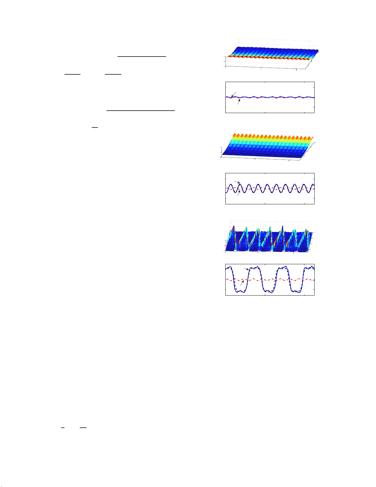
T ristabilit y in the p endula chain Ramaz Khomeriki 1 , 2 , J´ erˆ ome Leon 3 (1) Physics Dep artment, Tbilisi State University, 0128 Tbilisi (Ge or gia) (2) Max-Planck-Institut fur Physik komplexer Systeme, 01187 Dr esden (Germany) (3) L ab or atoir e de Physique Th ´ eorique et Astr op articules CNRS-IN2P3 (UMR5207), Universit ´ e Mont p el lier 2, 34095 Montp el lier (F r anc e) Exp erimen ts on a chain of coupled pendu la driv en perio dically at one end demonstrate th e ex- istence of a no vel regime whic h pro duces an o utpu t frequency at an o dd fraction of the driving frequency . The new stationary state is then obtained on numerical simulations and m o deled with an analytical solution of the contin uous sine-Gordon eq uation that resem bles a kin k -lik e motion back and forth in the restricted geometry of th e chai n. This solution differs from the expressions used to understand nonlinear bistability where the synchr onization c onstr ai nt w as the basic as sumption. As a result the short p endula chain is shown to p ossess tristable stationary states and to act as a frequency divider. P ACS num b ers: 05.45.-a, 05.45.Yv, 73.43.Lp I. INTRO DUCTION. The sine- Gordon model and its discr ete analogue , the F r enk el-Kontorov a chain, are among the most pr ominen t equations of nonlinear physics, and have a ttracted inter- est of people working in quite different fields, see e.g. bo oks [1, 2, 3]. In particularly , top ological (kinks) and nontopologic a l ( breather s ) so lutions of the sine- Gordon equation describe th e dynamics of nonlinear excitations in v ario us spatially mo dulated systems, e.g. dislo cations in c r ystals [4], magnetic and ferro electric doma in w alls motion [5 ], vortices in arr a ys of Jose phs on junctions [6], etc. A t the same time the mo del ha s a simple ex p eri- men tal counterpart, namely the chain o f linearly coupled pendula [3] which offers an int eresting opp ortunity to eas- ily visualize all the main nonlinear characteristics of the sine-Gordon system. T he n this simple lab orator y too l al- lows to observe nov el effects [7, 8, 9 , 10] which may then apply in completely different ph ysical situations. As a matter of fact, a recent exper imen tal dis c o v- ery of supra transmission effect in the p endula chain [11] has led to the study of similar phenomena in optical Bragg gr atings [12], Josephson Junction transmission line [13], wa veguide arrays [14, 15]. By this appro ac h, many similar phenomena observed in the same systems [16, 17, 18, 19, 20] hav e b een identified as effects of non- line ar bistabili ty . Mor eo ver it allow ed us to predict the existence of bistable ma g netization profiles in thin mag- netic films [21] and to s uggest ultra sensitiv e detectors (or dig ital amplifyers) in optical wav eguides [22] quan- tum Hall bilay ers [23] and J osephson Junction pa rallel arrays [2 4]. The bistability pro perty can b e simply for m ulated by saying that [25] a given p eriodic bo undary driving may pro duce tw o completely differen t stationary states: one which tends to the linear ev anescent pro file at v anishing amplitude, the other o ne which can b e qua litativ ely un- dersto od as a p ortion of the stationar y bre a ther-like so- lution which exists only if the system size is co mparable with the characteristic length o f the fundamental (co n- tin uous) breather so lution. This is a main difference with most o f the e arlier studies on sine- Gordon mo del where the semi-infinite chain has b een exa mined (see e.g. Ref. [26]). FIG. 1: Pictures of three stationary states of the p endula chai n obtained for one single given driv in g amplitude and frequency . The u pper graph correspond s to the low est en ergy state and th e lo wer one describ es the largest energy regime. An ap p ro ximate energy hierarc hy is 1:10:100. W e rep ort her e the discovery of a third stationar y state which can b e qualitatively understo o d a s the motion ba ck and forth o f a kink-like structure in the short pendula 2 chain. The new sta tionary regime ap ears to be com- pletely different fro m the tw o cases cons ide r ed earlie r e.g. in [21, 22, 2 3, 2 4, 2 5]. As a matter of fact, s uc h a dyna m- ics cr eates a new fr equency in the system and furnishes a to ol to divide the input frequency b y o dd fractions (we shall illustr ate chain end oscillations with frequency Ω / 3 or Ω / 5, wher e Ω is the driver frequency). The v alue of the o dd divider dep ends b oth on the input frequency range and o n the length of the chain. Let us recall that the pr eviously discovered tw o reg imes ar e s ynchr onize d to the driver (same input and output frequencies). II. MODEL EQUA TIONS. The dynamics of the chain of N p endula is na tur ally describ ed b y the F renkel-Kont orov a mo del [1] ¨ u n + δ ˙ u n − σ 2 ( u n +1 + u n − 1 − 2 u n ) + ω 2 0 sin u n = 0 , (1) where overdot means deriv a tion with resp ect to time. The v ariable u n is the angula r deviation of the n th pen- dulum, ω 0 is the eigenfrequency of a single pendulum and σ is prop ortional to the linear torsion co nstan t o f the spring (for our exp erimental chain ω 0 = 15 . 1 Hz, σ = 3 2 . 4 Hz). The damping co efficien t δ is phenomeno - logical, it ha s b een ev aluated in the exp eriments as ap- proximately δ = 0 . 01 ω 0 . This is the v alue ac tually used in the numerical s im ulations. The applied p erio dic dr iv- ing is here mo deled by the b oundary conditions u 0 ( t ) = b cos(Ω t ) , u N +1 = u N (2) which model a forced end in n = 0 a nd a free o ther end in n = N . It is worth insisting on the fa c t that the chain is sub- mitted to a pr escrib e d b oundary value (the da tum of u 0 ( t )), not to a given force a cting on the first particle. In the exp erimental setup, the motio n of the vir tual p en- dulum u 0 is the driving eng ine mo tion which has indeed a pr escribed motion obtained through feedback control. This has an imp ortant fundamental co nsequence: the en- ergy absorb ed by damping is con tinuoulsly comp ensated by the action of the driving and therefore the motion o f the c hain is quite similar to that of an undamped device (for which, in a s tationary regime, the driving w ould not give e ne r gy to the chain). The exp eriment co nsists th us in driving the short chain pictured in Fig.1 with a fre quency in the forbidden band gap (Ω < ω 0 ), whic h actually do es no t ex cite linear mo des. Without externa l pertur bation the system lo c ks to a p eriodic solution with low output amplitude u N ( t ). Depending on the v alue of an external kick one makes the system bifurcate to tw o different statio nary states and we th us obtain a tristable b eha vior (with approximate hier - arch y of e ne r gies 1:10 :100). The r e a der w ill find on the web page [27] a movie of the exp eriment where the sys- tem is firs t set in the high-ener g y new stationa ry stable regime and then put do wn succ e ssiv ely to the t wo other s stable states by taking energy off. 0 1 2 3 4 5 6 0 1 2 3 4 5 6 Input Amplitude |u 0 (t)| max (rad) Output Amplitude |u N (t)| max (rad) o o o Ω =0.9 ω 0 1 2 3 Ω =0.3 ω 0 II III I FIG. 2: An alytic inp ut-output amplitude dep endences for dif- feren t oscillation frequencies of stationary states given by for- mula s ( 5) where contin uous line represents solution (I), dot- ted line solution (I I) and dashed line solution (I II), plotted for tw o frequen cies , namely 0 . 9 ω 0 and 0 . 3 ω 0 as indicated. The p oin ts 1, 2 and 3 corresp onds to the stable regimes with a single driving amplitude | u 0 ( t ) | max = 0 . 5 rad. The p oints 1 and 2 represent the situations when the whole chai n oscillates with the driving amplitude 0 . 9 ω 0 but with different outpu t amplitudes. The p oin t 3 corresp onds t o the driv in g frequency 0 . 3 ω 0 and describ es kink motion forth and bac k. As the ex- p erimen ts and numerical sim ulations show (and this is a main finding of the pap er), the latter regime can also b e reached with a driving frequency 0 . 9 ω 0 three times larger than th e one actu all y used. T o dev elop an analytical descr iption of the proces s, let us consider the con tinuous approximation of eq.(1) by substitutions t → ω 0 t , n = ω 0 x/σ . Neglecting dis sipation we obtain the s ine - Gordon equation x ∈ [0 , L ] : u tt − u xx + s in u = 0 , (3) where L = N σ /ω 0 . The mixe d Dirichlet and Neumann Boundary Conditions u (0 , t ) = b sin(Ω t ) (driven b ound- ary), u x ( L, t ) = 0 (free end b oundary) allo ws to seek the following p erio dic stationary solutions [25] u ( x, t ) = 4 arc ta n r rs b X ( x ) T ( t ) , (4) where one has three c hoices (cn, sn and dn a re the stan- dard Jacobi elliptic functions) (I) X = cn( β ( x − L ) , µ ) , T = cn( ω t, ν ) , (II) X = dn( β ( x − L ) , µ ) , T = sn( ω t, ν ) , (5) (II I) X = dn( β ( x − L ) + K ( µ ) , µ ) , T = sn( ω t, ν ) . Here K ( µ ) stands for a complete elliptic integral of the first kind of mo dulus µ . These families o f solutions ar e parametrized by the tw o free constants ω and ν ∈ [0 , 1], then for solutions o f type (I) the r emaining par ameters 3 are given by b = ω 4 ν 2 (1 − ν 2 ) , s = ω 2 ν 2 2 r = 1 − ω 2 + 2 ω 2 ν 2 + p (1 − ω 2 ) 2 + 4 ω 2 ν 2 , β 2 = b + r 2 r , µ 2 = r 2 b + r 2 , (6) while in b oth cases (II) and (I II) they read b = ω 4 ν 2 , s = − ω 2 ν 2 , 2 r = 1 − ω 2 (1 + ν 2 ) + p [1 − ω 2 (1 + ν 2 )] 2 − 4 ω 4 ν 2 , β 2 = r, µ 2 = 1 − b r 2 . (7) Note tha t r should b e real v alued and p ositive which may restrict the allowed v alue s o f ω . II I. T RI- ST ABILITY AND F REQUENCY DIVISION. Since the exp eriments (confirmed by num erical simu- lations later on) show that the fr equency Ω / 3 ca n also be excited, we assume that the p erio d of the time dep en- dent pa rt T ( t ) of the s ta tionary solutions (5) coincide with a n o dd integer fractions of the driving frequency Ω. Recalling that the p erio d of T ( t ) is 4 K ( ν ) /ω we r e q uire th us ω = 2Ω K ( ν ) / ( mπ ) . (8) where m is an o dd integer. F or a g iv en v alue o f the pa- rameter ν ∈ [0 , 1], the ab ov e relatio n fixes the seco nd parameter ω in terms of the driving frequency Ω. There- fore fixing Ω (driver fr equency) and v a rying ν one ca n plot the output amplitude u ( N , t ) in terms of the input u (0 , t ) from the analytic expre ssions (5). W e display this depe ndence for Ω = 0 . 9 (in units of ω 0 ) a s a the full line in fig.2 wher e different co lors rep ort to different so- lutions. W e also plot (dashe d line ) the output amplitude for a driving frequency Ω = 0 . 3. Therefore, to the given driver amplitude max t | u (0 , t ) | = 0 . 5 may cor respond tw o stable sync hronized states (points 1 a nd 2 on the graph) having the driver frequency 0 . 9 and one more sta ble state with frequency 0 . 3. It is then a simple matter to chec k that the stationa ry state related to p oin t 3 of the plot of fig.2 cor respo nds effectively to our numerical sim ulations, and hence to the exp eriments of fig.1. It is done in fig.3 where the last plot shows the result of a numerical sim ulation (full line) c o mpared w ith the analytic solution (dahsed line) related to po in t 3 of fig.2. W a ha ve a ls o plotted the time evolution of the total energ y of ea c h p endulum given b y E n = 1 2 ˙ u 2 n + σ 2 4 ( u n +1 − u n ) 2 + ( u n − 1 − u n ) 2 + ω 2 0 (1 − cos u n ) . (9) 0 2 4 2 4 6 8 0 0.05 0.1 Pendulum Number Energy 0 2 4 −5 0 5 Displacement Angle [rad] Time [s] Time [s] u 8 (t) u 0 (t) 1) 0 2 4 2 4 6 8 0 2 4 Pendulum Number Energy 0 2 4 −5 0 5 Displacement Angle [rad] Time [s] Time [s] u 8 (t) u 0 (t) 2) 0 2 4 2 4 6 8 0 20 40 Pendulum Number Energy 0 2 4 −5 0 5 Displacement Angle [rad] Time [s] Time [s] u 8 (t) u 0 (t) 3) FIG. 3: Numerical sim ulations on F renkel-Kon torov a mo del (1) with a d amping constant δ = 0 . 01 ω 0 and 8 p endula. The time evolution of p endula energy and input-ou t put oscilla- tions are display ed corresponding to the p oin ts 1), 2) and 3) in Fig. 2. The driving amplitude is | u 0 ( t ) | max = 0 . 5 rad and its frequency Ω = 0 . 9 ω 0 for all 3 cases. This results in the same ou t put frequency oscillations Ω in gra phs 1) and 2) but Ω / 3 out put oscillations in graph 3). Dashed lines dis- pla y analytical curves obtained from (5), while dotted-d ashed and solid lines represent time evol ution of in p ut and out put oscillatio ns, resp ectiv ely . The n umerical simulations o f the proces s are done b y applying to the mo del (1) the boundar y conditions (2) with b = 0 . 5 and ω = 0 . 9 ω 0 , together with an initial condition where a few p endula a t the end of the c hain are given la rge initial amplitude. F or instance, to rea c h the new stationa ry state (3) of fig.3, the chosen initial 4 amplitude is 2 π , while fo r the v alue π , the system lo c ks to the state (2). It is worth noting that b oth exp e rimen ts (as those dis- play ed in [27]) and numerical simulations contain intrin- sic damping. Still the analytic s olutions o f the co n tin uous undampe d sine-Gordo n mo del fit strikingly well numeri- cal simulations of the dis c rete damp ed F r enk el-Kontorov a mo del (1). This is a gener al prop erty o f such short lengt h driven systems to lo ck o n fundamental solutio ns of the undampe d limit, as previo us ly display ed in [23, 24, 2 8]. The main fac t is that, without da mping , the chain in a stationary regime do es not a bsorb energy and the b ound- ary v alue do es not tr ansfer any p ow er to the chain. With damping, the dr iv ing b oundary do es transmit p ow er to the chain in such a way as to compe nsate exactly the losses. The p oin t is that the system is submitted to a pr escrib e d b oundary value which adapts to the amount of lost pow er and keeps amplitude and frequency co ns tan ts (in the ex periments presented in fig.1, the engine has a feedback driving mechanism that controls the amplitude and frequency). Last, the pro of that the analytical solu- tions co nstitute an attra c to r for the damp ed system is, as far as we kno w, an ope n question. 0 2 4 4 8 12 0 20 40 Pendulum Number 0 2 4 −5 0 5 Displacement Angle [rad] Energy Time [s] Time [s] u 12 (t) u 0 (t) 0 2 4 4 8 12 0 10 20 Energy 0 2 4 −5 0 5 Displacement Angle [rad] Pendulum Number Time [s] Time [s] u 12 (t) u 0 (t) FIG. 4: Time evolution of p endula energy and input-outp ut oscillatio ns for the c hain consisting of 12 p endula. As seen one gets the frequen cy d ivisio n on 5 at the out p ut with resp ect to the inp ut frequency when the input frequency is Ω = 0 . 9 ω 0 (upp er graph) . I n the low er graph the driving frequency is Ω = 0 . 5 ω 0 and one has frequ ency division b y factor 3. Thu s w e ha ve actually demonstrated the possibility o f conceiving a fr e qu ency di vider with whic h the dr iving frequency c a n b e divided by 3 , 5 , 7 , dep ending on the chain length. F or example the fig.4 shows numerical sim- ulations o n a chain of 12 p endula with a resulting fre- quency divis io n by 5 a t a driving frequency 0 . 9 ω 0 and by 3 a t a dr iving frequency 0 . 5 ω 0 . In such a case we hav e o btained that the frequency is divided by 5 if the driving freq ue nc y Ω is in the range 0 . 88 ω 0 < Ω < 0 . 92 ω 0 , while the same chain can divide the frequency by 3 when 0 . 41 ω 0 < Ω < 0 . 6 ω 0 . IV. CONCLUSION. F o r a single mono chromatic driving (fi xed ampli- tude a nd frequency), we hav e demonstrated exp erimen- tally and n umerically the existence three states which hav e bee n g iv en analy tic e xpressions (in the contin uous limit): the first o ne is the quasi-linear solution (actu- ally a breather- like tail), the sec ond one resembles half a br e ather , b oth of them oscillating with the driving fre- quency Ω, and which were a lready known a s the build- ing blo c ks of no nlinear bistability . The discov ered thir d state r esem bles a kink moving back and forth with the frequency Ω / 3 . The s e sa tes have b een g iven explicit ana- lytical ex pressions in the contin uous limit: the fir st state is describ ed b y the solution of type (I II) in (5) while the s olution of t ype (I) desc ribes altogether the “half - br e ather” with frequency Ω and the “oscil lating kink” with frequency Ω / 3. The pro cess of freq uency division is th us induced b y the motion back a nd for th of a kink-like structur e inside the chain. It is p ossible to extend these studies to other realistic physical systems gov erned by the sine-Gordon equation. W e exp ect such a new stationar y stable r egime to be int eresting for applications where o ne is interested in pro ducing an odd fr a ction of the driving frequency . The fraction num b er dep ends b oth on the length of the chain a nd on the input frequency rang e. Last but not lea st, many other well known no nlinear systems exhibit nonlinea r bista ble behavior, a s e.g. the nonlinear Schr¨ odinger eq uation or the coupled mo de sys- tem in Bra gg media, and this discov ery is very likely to apply also there. V. ACKNO WLEDGEMENTS. W e thank Dominique Chevriaux for the pro duction o f the movie on the p e ndula chain. R. K h. ackno wledges financial supp o rt of the Georgian National Science F oun- dation (GrantNo GNSF/STO7/4-197 ) and USA Civil- ian Research and Dev elopment F oundation (a ward No GEP2-2 848-TB-06 ). 5 [1] O.M. Braun , Y u.S. Kivshar, The F r enkel-Kontor ova Mo del: Conc epts, M eth o ds, and Appl i c ations , (Sp ringer- V erlag, Berlin, 2004). [2] M. Remoissenet, Waves Cal le d Solitons (Sp ringer, Berlin, 1999) [3] A.C. Scott, Nonline ar Scienc e , 2-nd ed ition. (Oxford Uni- versi ty Press, New Y ork, 200 3). [4] M. El-Batanouny , S. Burdick, K. M. Martini, P . Stan- cioff, Phys. R ev. Let t . 58 , 2762 (1987) [5] Xin Liu, Xiong-Jun Liu, Mo-Lin Ge, Phys. R ev . B, 71 , 224419 (200 5). [6] J. Pfeiffer, A. A. Ab dumaliko v , M. Sc huster, A . V. U sti- nov, Phys. R ev. B, 77 , 02451 1, (2008). [7] R. Chacon, P . J. Martinez, Phys. Rev. Lett. 98 , 224102 (2007) [8] N. V . Alexeev a, I. V. Barashenko v, G. P . Tsironis, Ph ys. Rev. Lett. 84 , 3053 (2000) [9] W. Chen, B. H u, H. Zhan g, Phys. Rev. B, 65 , 134302, (2002). [10] Y u. A. Kosevich, L. I. Manevitc h, A. V . Savin, Phys. Rev. E, 77 , 046603 (2008). [11] F. Geniet, J. Leon, Ph ys. Rev. Lett. 89 , 134 102 (2002). [12] J.Leon, A. Sp ire, Phys. Lett. A, 327 , 474, (200 4). [13] F. Geniet, J. Leon, J. Phys. Condens. Matter, 15 , 2933 (2003) [14] J. Leon, Phys. R ev. E, 70 , 05660 4 (2004) [15] R. Khomeriki, Phys. R ev. Lett., 92 , 063905 (2004) [16] H.G. Winful, J.H. Marburger E. Garmire, A ppl. Phys. Lett., 35 , 379, (1979 ) [17] W. Chen, D.L. Mills, Phys. Rev . B., 35 , 524, (1987) [18] O.H. Olsen, M.R. S am uelsen, Phys. Rev . B., 34 , 3510, (1986) [19] D. Barda y , M. Remoissenet, Ph ys. Rev. B., 41 , 10387, (1990) [20] Y.S. Kivshar, O.H . Olsen, M.R. S am uelsen, Phys. Lett. A, 168 , 391, (1992) [21] R. Khomeriki, J. Leon, M. Manna, Ph ys. Rev . B, 74 , 094414, (2006). [22] R. Khomeriki, J. Leon, Phys. Rev. Lett., 94 , 2439 02, (2005) [23] R. Khomeriki, D. Chevriaux , J. Leon, Eur. Phys. J. B, 49 , 213 (2006). [24] D. Chevriaux, R. Khomeriki, J.Leon, Phys. Rev. B, 73 , 214516 (200 6). [25] R. Khomeriki, J. Leon, Phys. Rev. E., 71 , 056620, (2005). [26] M.D. Miller, Phys. R ev . B, 33 , 164 1 (1986). [27] http://www .lpta.univ-montp2.fr/users/le on/Bistable/ [28] K. Tse V e Koon, J. Leon, P . Marqui, P . Tc hofo-Dinda, Phys Rev E 75 (200 7) 066604
Original Paper
Loading high-quality paper...
Comments & Academic Discussion
Loading comments...
Leave a Comment