Information Theoretic Operating Regimes of Large Wireless Networks
In analyzing the point-to-point wireless channel, insights about two qualitatively different operating regimes--bandwidth- and power-limited--have proven indispensable in the design of good communication schemes. In this paper, we propose a new scali…
Authors: Ayfer Ozgur, Ramesh Johari, David Tse
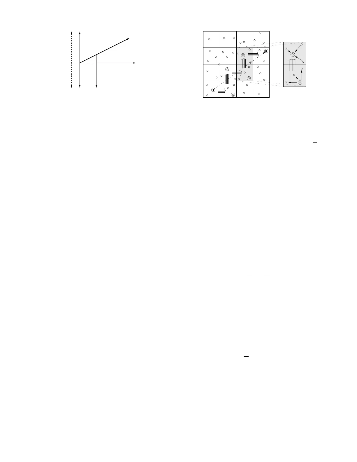
1 Information Theoretic Operating Regim es of Lar ge W ireless Networks A yfer ¨ Ozg ¨ ur , Ramesh Jo hari, Membe r , IEEE , David Tse, F ellow , IEEE and Olivier L ´ ev ˆ eque, Membe r , IEEE Abstract — In analyzing the point-to-point wireless channel, insights about two qualitativ ely different operating r egimes— bandwidth- and power -limit ed—hav e prov en in dispensable in the design of good communication schemes. In this paper , we p ropose a new scaling law f ormulation fo r wireless netw orks that allows us to d ev elop a th eory that is analogous to the point-to-point case. W e identify fu ndamental operating regimes of wi reless netwo rks and derive architectural guidelines for the d esign of optimal schemes. Our analysis shows that i n a given wireless n etwork with arbi- trary size, area, power , bandwidth , etc., there are th ree param- eters of imp ortance: th e short-di stance SNR, the long-distan ce SNR, and the power path loss exponent of the env ironment. Depending on these parameters we identi fy f our qualitatively different regime s. One of these regimes is especially interesting since it is fundamentally a consequence of the heterogeneous nature of li nks i n a network and does not occur in the point-to- point case; the network capacity is both power and b andwidth limited. This reg ime has thus f ar remained hidd en due to the limitations of th e existing formulation. Existing schemes, eith er multihop transmission or hierarchical cooperation, fail to achieve capacity in this regime; we propose a new hybrid scheme th at achiev es capacity . Index T erms — Ad hoc Wireless N etworks, Distributed M IMO, Hierarchical Cooperation, Mu ltihoppin g, Operating Regimes, Scaling Laws. I . I N T RO D U C T I O N The classic c apacity fo rmula C = W log 2 (1 + P r / N 0 W ) bits/s of a p oint-to-p oint A WGN chann el with ban dwidth W Hz, r eceiv ed power P r W atts, and white n oise with power spectral density N 0 / 2 W atts/Hz plays a central role in co m- munication system d esign. The fo rmula not only quantifies ex- actly the performanc e limit o f c ommun ication in terms o f sys- tem par ameters, but per haps more impor tantly also id entifies two fun damentally different oper ating regimes. In the power - limited (o r low SNR) regime, wh ere SNR := P r / N 0 W ≪ 0 The work of A yfer ¨ Ozg ¨ ur wa s support ed by Swiss NSF grant Nr 200020- 118076. The work of Ramesh Johari was supported by the Defense Advance d Researc h Projects Agency under the ITMAN ET program, and the U.S. Nationa l Science Foundat ion under grant 0644114. The work of David Tse was sup ported by the U.S. Nationa l Science Found ation via an ITR grant: “The 3R’ s of Spectrum Manage ment: Reuse, Reduce and Recycle ”. The material in this paper was presented in part at the IEEE Symposium on Informat ion Theory , T oronto, July 2008. A. ¨ Ozg ¨ ur and O. L ´ ev ˆ eque are with the Ecole Polytechni que F ´ ed ´ eral e de Lausann e, Fac ult ´ e Informati que et Communications, Build- ing INR, Stat ion 14, CH - 1015 Lausanne, Switzerl and (e-mails: { ayfer .ozgur , oli vie r .leveque } @epfl.ch). R. Johar i is with the Stanfo rd Uni ver sity , Depart ment of Manage- ment Science and Engineering, Stanford, CA 943 05, USA (e-mail: ramesh.johari @stanford .edu). D. Tse is with the Uni versi ty of Californ ia at Berkele y , Depart ment of EECS, Berkele y , CA 94720, USA, (e-mail: dtse@ee cs.berk ele y .edu). dB, the capacity is ap proximate ly linear in the power and the per formanc e depe nds critically on the po wer a vailable but not so much on the ba ndwidth. In the band width-limited (or high SNR) regime, wh ere SNR ≫ 0 dB, the cap acity is approx imately linear in the bandwidth an d th e p erform ance depend s critically o n the bandwidth but not so much o n the power . The regime is determined by the interplay between the amo unt of p ower and degre es of freedom av ailable. Th e design o f g ood co mmunica tion schemes is primar ily driven by the param eter regime one is in. Can an alogou s op erating regimes be identified fo r ad hoc wireless networks, with multiple source and d estination pairs and no des relay ing inform ation for each other? T o ad dress this question, we are c onfron ted with several pro blems. First, we have no exact formu la for the capacity of network s, even in the simp lest case o f a sing le source-de stination pair plus o ne relay . Second, unlike in the poin t-to-poin t case, ther e is no single received SNR param eter in a n etwork. The ch annels between nod es closer together can be in th e high SNR r egime while those between nodes farther aw ay can be in the low SNR regime. One approa ch to get aro und the first problem is through the scaling law for mulation. Pione ered by Gup ta and Kumar [ 1], this appro ach seek s not the exact cap acity of the network but only ho w it scales with the number of nodes in the netw ork and the nu mber o f sour ce-destination pairs. The c apacity scaling turns out to depend critically on how the area o f the ne twork scales with the nu mber of nod es. T wo network models have been c onsidered in th e liter ature. I n dense n etworks [1], [2], [9], the area is fixed while th e den sity of th e no des increases linearly with th e nu mber of nodes. In extended networks [ 3], [4], [ 5], [6], [7], [ 8], [9], the area g rows linearly with the number of nodes while the density is fixed. For a given path loss exponent, the area of the network d etermines the amo unt of p ower that can be tran sferred acro ss the n etwork and so these different scalings cou ple the power tra nsferred an d the number of nodes in different ways. There are two sign ificant lim itations in using the existing scaling law results to id entify fu ndamen tal operating regimes of ad ho c networks. First, the degrees of freedom a vailable in a network depen d o n the numb er o f nodes in ad dition to the the amoun t of bandwid th available. By a p riori couplin g the power transferred in the network with the numbe r of node s in specific ways, the existing formulation s ma y be missing out on mu ch of th e interesting parameter space. Second, neither dense nor extended networks allow us to m odel the co mmon scenario where the channels between different no de pairs can be in different SNR re gimes. More concretely , let us interpret a 2 channel to be in hig h SNR in a large n etwork if th e SNR go es to infinity with n , and in low SNR if the S NR goes to zero wit h n . 1 Then it can be r eadily verified that in de nse ne tworks, the channels b etween all node p airs are in th e high SNR regime, while in extended n etworks, the cha nnels between all node pairs are in the low SNR regime. In this paper, we con sider a g eneralization that allows us to overcom e these two limitations o f the existing formulation. Instead o f con sidering a fixed area or a fixed density , we let the area of the network scale like n ν where ν can take on any real value. Dense n etworks correspon d to ν = 0 and extended networks correspo nd to ν = 1 . By analyzing th e problem fo r all possible values of ν , we are now considering all possible interplay between power and degrees of freedom . Note that in networks wher e ν is strictly between 0 and 1 , channels between nod es that are far away will be at lo w SNR wh ile n odes that are closer by will be at high SNR. Indeed , the distance between nearest neigh bors is of the order of p A/n = n ( ν − 1) / 2 and, assuming a path loss expo nent of α , the received SNR of the transmitted signal from the nearest neigh bor scales like n α (1 − ν ) / 2 , growing with n . On the othe r hand, the received SNR of the tra nsmitted signal from the farthest nodes scales like ( √ A ) − α = n − αν / 2 , going to zer o with n . Note that scaling the ar ea by n ν is completely equiv alent to scaling the ne arest ne ighbor SNR as n β , wher e β := α (1 − ν ) / 2 . Since SNR is a physically more rele v ant param eter in designing co mmunicatio n systems, we will formulate the problem as scaling directly the n earest neighbo r SNR . The m ain result of this pap er is as follows . Consider 2 n nodes random ly located in an area 2 A such that the received SNR for a transmission over the typical nearest neigh bor distance of p A/n is SNR s := n β . The path loss expon ent is α ≥ 2 . Each transm ission go es thr ough an indep endent unifor m phase ro tation. There are n source and d estination pairs, ra ndomly chosen, each demandin g the same rate. Let C n ( α, β ) denote the total capacity of the network, which is the highest achievable sum rate, in bits/s/Hz and its scaling exponent be d efined as, e ( α, β ) := lim n →∞ log C n ( α, β ) log n . (1) The fo llowing theo rem is the main r esult of this pa per . Theor em 1: The scaling exponen t e ( α, β ) o f the total ca- pacity C n ( α, β ) is given by e ( α, β ) = 1 β ≥ α/ 2 − 1 2 − α/ 2 + β β < α/ 2 − 1 an d 2 ≤ α ≤ 3 1 / 2 + β β ≤ 0 and α > 3 1 / 2 + β / ( α − 2) 0 < β < α/ 2 − 1 an d α > 3 . (2) Note that dense ne tworks corr espond to β = α/ 2 , with an exponent e ( α, α/ 2) = 1 (first case), and extended networks 1 W e interpret a channel in both high and lo w SNR, if the SNR does not depend on n . correspo nd to β = 0 , with an expo nent equal to: e ( α, 0) = 2 − α/ 2 2 ≤ α ≤ 3 1 / 2 α > 3 (second and thir d cases r espectiv ely). These special cases are the main r esults of [9]. Ob serve tha t in the general case the scaling exponent e ( α, β ) depends o n the path loss exponent α an d the nearest neigh bor SNR exponent β separately , so the gen eral result canno t be obtain ed by a simple re-scaling of distance s in the dense or extended mode l. T o inte rpret the g eneral result (2) an d to c ompare it to th e point-to- point scenario, let u s re -express the result in term s of system quantities. Recall that SNR s is the SNR over th e smallest scale in the n etwork, which is the typical near est neighbo r d istance. Thu s, SNR s = n β = P r N 0 W , (3) where P r is the received power from a no de at the typical nearest n eighbor distance p A/n and W Hz is the ch annel bandwidth . Let us also define the SNR over the largest scale in the network, the dia meter √ A , to be SNR l := n n − α/ 2 P r N 0 W = n 1 − α/ 2+ β , (4) where n − α/ 2 P r is the received p ower fr om a node at distance diameter of the network. T he result (2) can b e u sed to give the following appro ximation to the total capacity C , in b its/s: 2 C ≈ nW SNR l ≫ 0 dB n 2 − α/ 2 P r / N 0 SNR l ≪ 0 dB and 2 ≤ α ≤ 3 √ nP r / N 0 SNR s ≪ 0 dB and α > 3 √ nW α − 3 α − 2 ( P r / N 0 ) 1 α − 2 SNR l ≪ 0 dB , SNR s ≫ 0 dB and α > 3 . (5) Note two imm ediate ob servations in ( 5). First, there are two SNR p arameters of interest in networks, the short and the long distance SNR’ s, as opposed to the po int-to-po int ca se where there is a single SNR pa rameter . Second, the m ost n atural way to measure the long- distance SNR in networks is not the SNR of a pa ir separated by a distance equal to th e diame ter of the network, but it is n times this qu antity as defined in (4). Note that ther e ar e o rder n nod es in total located at a diameter distance to any given nod e in the network, hence n times the SNR between f arthest nodes is the total SNR that can be tr ansferred to this n ode a cross th is large scale. On the o ther hand a no de has only a co nstant number o f nearest neigh bors, and h ence the short-d istance SNR in (3) is simply the SNR between a nearest n eighbor pair . The four regimes in (5 ) are shown in Figur e 1. In Regime- I, the performa nce is achieved by hierarchical cooperation and long range MIMO tran smission, the scheme intr oduced in [9]. At th e high est level of h ierarchy , clusters o f size alm ost order n c ommunic ate via MIMO, at d istance the d iameter of the n etwork. The qu antity SNR l correspo nds to the total 2 Note that C = W C n ( α, β ) . 3 2 3 α Regime β 0 β = α/ 2 − 1 Regime I II Regime IV Regime III Fig. 1. The four operat ing regi mes. The optimal s chemes in these regimes are I-Hierarc hical Coope ratio n, II-Bursty Hierarchic al Cooperat ion, III-Multihop, IV - Multihop MIMO Hierarchic al Cooperatio n. received SNR at a n ode d uring the se MIM O transmissions. Since th is q uantity is larger than 0 dB, the long range MI MO transmissions, and hence the perform ance of the network, are in the bandwidth limited regime, with p erforma nce roughly linear in the b andwidth W . The perfo rmance is linear in the nu mber of nod es, implying tha t interfer ence lim itation is removed by coop eration, at least as far as scaling is co ncerned . Performan ce in this regime is qu alitativ ely th e same a s that in dense network s. In all the oth er regimes, the total lon g-range receiv ed SNR is less tha n 0 dB. Hence we are power -limited and the tra nsfer of power becom es impor tant in deter mining pe rforman ce. I n Regime-II, i.e., whe n α ≤ 3 , signal p ower decays slowly with distance, a nd the total power transfe r is maximized by lo ng- range MIMO tr ansmission. This per formanc e can be achieved by bursty hier archical coo peration with long-rang e MIMO, much like in extended networks. When α > 3 , signal power dec ays fast with d istance, and the transfer of power is maximized b y short-range comm u- nications. If th e n earest-neigh bor SNR ≪ 0 d B (Regime- III), these transmissions are in the power -efficient r egime and this p ower gain tran slates linea rly into capacity , so nearest- neighbo r multih op is optimal. This is in deed the case in extended networks, and hen ce nearest-n eighbo r multih op is optimal fo r extended networks whe n α > 3 . The mo st interesting case is th e fourth regime , wh en α > 3 and 0 < β < α/ 2 − 1 . This is th e case wh en SNR s ≫ 0 dB, so nearest-neig hbor transmission s are bandwidth -limited and n ot power -efficient in translating th e power gain into capacity g ain. There is the pote ntial of increasing throug hput by spatially multiplexing transmission via coop eration within clu sters of nodes and perform ing distributed MI MO. Y et, the cluster s cannot be as large as the size of the network since power attenuates rap idly for α > 3 . Indeed , it turn s out th at the o ptimal scheme in this regime is to coo perate hierarchica lly within clusters of an in termediate size, perfor m MIMO tran smission b etween adjacent clusters and then multiho p across se veral clusters to get to the final destination. (See Figure 2). T he optima l cluster size is cho sen such that the r eceiv ed SNR in the MIMO tran smission is at 0 dB. Any smaller cluster size results in power in efficiency . Any larger cluster size r educes the amount of power transfer because of th e attenua tion. No te that the two extremes o f this architecture are p recisely th e traditional m ultihop sche me, S D Fig. 2. The figure illustra tes the optimal scheme in Reg ime IV which is based on cooperating locally and multihopping global ly . Note that packet s are transmitt ed by multihopp ing on the netw ork lev el and each hop is reali zed with distrib uted MIMO transmissions combined with hie rarchi cal cooperation . where the cluster size is 1 and th e number of hops is √ n , and the long -range c ooperative sche me, where the cluster size is of or der n and the number of hops is 1 . Note also th at beca use short-ran ge links are band width-limited and lon g-rang e link s are p ower -limited, th e n etwork capacity is both bandwidth and power-limited. Thu s the ca pacity is sensiti ve to bo th the amount of b andwidth an d th e am ount of p ower av ailable. This regime is fundam entally a consequ ence of th e heterogen eous nature of link s in a network and does no t o ccur in point- to- point link s, nor in dense o r extend ed n etworks. The o rganization of the paper is as fo llows . In the fo llowing section we pre sent our mo del in more detail. S ection III der i ves a tight u pper bound o n the scaling expo nent in (1). Section IV introdu ces schemes that ac hiev e the up per bound p resented in the previous section. The two sections together prove our main result in Theorem 1. Section V contains our con clusions. I I . M O D E L There are 2 n nodes unifo rmly and indep endently distrib uted in a rec tangle of ar ea 2 √ A × √ A . Half of the nodes ar e sources an d the other half a re d estinations. The sources and destinations are ran domly paired up one-to-o ne without any consideratio n on node locations. Each source has th e same traffic r ate R in bits/s/Hz to send to its destinatio n node and a common a verage transmit power b udget of P W atts. The total throug hput of the system is T = nR . W e assume that commun ication takes place over a flat channel of bandwidth W Hz around a carrier frequency of f c , f c ≫ W . The comp lex baseban d-equivalent chann el gain between nod e i and nod e k at time m is g i ven by: H ik [ m ] = √ G r − α/ 2 ik exp( j θ ik [ m ]) (6) where r ik is the distance between the node s, θ ik [ m ] is the random phase at time m , unifor mly distributed in [0 , 2 π ] and { θ ik [ m ]; 1 ≤ i ≤ 2 n, 1 ≤ k ≤ 2 n } is a collection of ind ependen t iden tically distributed random processes. T he θ ik [ m ] ’ s and the r ik ’ s are also assumed to be independ ent. The par ameters G and α ≥ 2 are a ssumed to be con stants; α is called the power path loss expon ent. The path-lo ss model is based on the stan dard far-field as- sumption: we assume th at the distance r ik is much larger than the carrier wa velength λ c . When the distances are com parable 4 or shorter than the carrier wav elength, the simple path-loss model obviou sly do es not hold anym ore as path loss can potentially become path “gain”. M oreover , th e ph ases θ ik [ m ] depend on the distance between th e nodes modulo the car rier wa velength a nd they ca n only be modeled as completely random and indepen dent of th e actual po sitions of the nod es if the nod es’ separation is large enoug h. Indeed, a recent result [10] showed that, without makin g an a priori assumption of i.i.d. phases, the degrees of free dom ar e limited by the diameter o f the n etwork (nor malized by the car rier wav elength λ c ). This is a spatial limitation an d holds regardless of h ow many comm unicating node s there are in the network. Th is result suggests that as long as the number of nodes n is smaller than this norma lized d iameter , the spatial d egrees of fr eedom limitation does no t k ick in, the degrees of freed om are still limited by the number of nod es, and the i.i.d. pha se model is still reason able. For example, in a network with diameter 1 km and carrier fr equency 3 GHz, the numb er of nod es should be of the ord er of 10 4 or less for the i. i.d. ph ase model to be vali d. While the pr esent pape r d eals exclusively with the standard i. i.d. r andom phase mo del, it would be interesting to apply o ur new scaling law formulatio n to incor porate regimes where ther e is a spatial degree s of freed om limitation as well. Note th at the channel is random, dep ending on the location of the user s an d th e ph ases. Th e locatio ns are assumed to be fixed over the dur ation of the commu nication. The phases are assumed to vary in a stationar y ergodic man ner (fast fading) . W e assum e that th e phases { θ ik [ m ] } are known in a casu al manner at all the no des in the ne twork. T he signal received by no de i at time m is giv en by Y i [ m ] = X k 6 = i H ik [ m ] X k [ m ] + Z i [ m ] where X k [ m ] is the signal sent by no de k at time m and Z i [ m ] is white circularly symm etric Gaussian n oise of variance N 0 per symb ol. I I I . C U T S E T U P P E R B O U N D W e consider a cut d i viding the network area in to two eq ual halves. W e are interested in upper boundin g the sum of the rates o f commu nications T L → R passing thro ugh the cut from left to right. These c ommun ications with source nodes located on the le ft and destination nodes loc ated o n th e rig ht h alf domain are d epicted in bold lines in Fig. 3. Since the S-D pairs in the network are f ormed u niformly at ra ndom, T L → R is equal to 1 / 4 ’th o f th e total thr oughp ut T w .h.p. 3 The maximum achievable T L → R in bits/s/Hz is bounded a bove by the capac ity of the MIMO ch annel between all nod es S located to th e lef t of the cut an d all nod es D loc ated to the right. Un der the fast fading assumption , we have T L → R ≤ max Q ( H ) ≥ 0 E ( Q kk ( H )) ≤ P , ∀ k ∈ S E log det( I + 1 N 0 W H Q ( H ) H ∗ ) (7) 3 with high probabilit y , i.e., with probabilit y going to 1 as n grows. D S y ˆ w x E V D Fig. 3. The cut-set considered in Section III. The communicat ion reque sts that pass across the cut from left to right are depicted in bold lines. where H ik = √ G e j θ ik r α/ 2 ik , k ∈ S, i ∈ D . The map ping Q ( · ) is from th e set of possible ch annel realiza- tions H to the set of p ositi ve semi-definite tr ansmit covariance matrices. Th e diagonal element Q kk ( H ) correspon ds to the power allocated to the k th n ode for chann el state H . Let us simplify no tation by in troducing SNR s := GP N 0 W ( A/n ) α/ 2 (8) which can be inter preted as the average SNR b etween near est neighbo r nodes since p A/n is the typica l near est neighbo r distance in the network. Let us also rescale the distances in the network by this nearest neig hbor distance, de fining ˆ r ik := 1 p A/n r ik and ˆ H ik := e j θ ik ˆ r α/ 2 ik . (9) Note that the first tra nsformation rescales space and m aps our original network of area 2 √ A × √ A to a network of area 2 √ n × √ n , referr ed to as an extended network in the literature. Consequently , the matrix ˆ H defined in ter ms o f the rescaled distances relates to such a n extended n etwork with area 2 n . W e can r e write (7) in terms of these new v ariables as T L → R ≤ max Q ( ˆ H ) ≥ 0 E ( Q kk ( ˆ H )) ≤ 1 , ∀ k ∈ S E log det( I + SNR s ˆ H Q ( ˆ H ) ˆ H ∗ ) . (10) In order to upp er bound (10), we will use an appro ach similar to the one d ev eloped in [9, Sec.V -B] for analyzing the capa city scaling of extended networks. Note that although due the rescaling in ( 9), ˆ H in (10) governs an extend ed network, the problem in (10) is n ot e quiv alent to the classical extended setup since her e we do not necessarily assume SNR s = 1 . Indeed , we want to keep full gen erality and av oid such arbi- trary assumption s on SNR s in the cu rrent paper . Formally , we are interested in cha racterizing th e whole regime SNR s = n β where β can be any real nu mber . One way to up per boun d (10) is throu gh upper boundin g the capacity b y the to tal received SNR, f ormally using th e relation log det( I + SNR s ˆ H Q ( ˆ H ) ˆ H ∗ ) ≤ T r SNR s ˆ H Q ( ˆ H ) ˆ H ∗ . (11) 5 The upper bound is tig ht o nly if th e SNR r eceiv ed by each right-ha nd side nod e (each diagona l entry of the matrix SNR s ˆ H Q ( ˆ H ) ˆ H ∗ ) is small. (No te that th e relation in (11) relies on the ine quality lo g(1 + x ) ≤ x which is o nly tigh t if x is small.) In the extended setup, wh ere SNR s = 1 , the network is high ly power-limited a nd the r eceiv ed SNR is small, that is decays to ze ro with increasing n , fo r every rig ht-hand side node. Using (11) yield s a tight upper bound in that case. Howe ver , in the g eneral ca se SNR s can be arbitrar ily large which can r esult in h igh received SNR for certain right-han d side nodes that are lo cated close to the cu t or even f or all nodes, dependin g on how large exactly SNR s is. Hence, before using ( 11) we n eed to distinguish between those right-h and side n odes that receive high SNR and those that ha ve poor power co nnection s to the lef t-hand side. For the sake of simp licity in presentation, we assume in this section that there is a rectan gular region located immediately to the right of the cut that is c leared o f nodes. Formally , we assume that the set of nodes E = { i ∈ D : 0 ≤ ˆ x i ≤ 1 } is empty , where ˆ x i denotes the ho rizontal coordinate of the rescaled position ˆ r i = ( ˆ x i , ˆ y i ) of node i . In fact, w .h.p this proper ty does not hold in a random r ealization o f th e n etwork. Howe ver , makin g this assumption allows u s to exhibit the central ideas of the discussion in a simpler manner . The extension of the analysis to the gene ral case (witho ut this particular assump tion) is giv en in Appen dix I. Let V D denote the set o f n odes lo cated on a rec tangular strip immediate ly to the right of the emp ty region E . Formally , V D = { i ∈ D : 1 ≤ ˆ x i ≤ ˆ w } where 1 ≤ ˆ w ≤ √ n and ˆ w − 1 is the r escaled wid th of the rectangu lar strip V D . See Fig . 3. W e would like to tune ˆ w so that V D contains the righ t-hand side nod es with h igh received SNR; i.e., th ose with r eceiv ed SNR larger than a thresho ld, say 1 . Note howev er that we d o not yet k now the c ov ariance matrix Q of the tran smissions from the left-hand side nodes, which is to be determined f rom the maximizatio n prob lem in (10). Thu s, we cannot c ompute the received SNR of a right-h and side n ode. For the pu rpose of determinin g V D howe ver , let u s a rbitrarily look at th e case when Q is the identity matrix and define the received SNR of a r ight-han d side node i ∈ D when left-han d side no des are transmitting indep endent signals at full p ower to be SNR i := P N 0 W X k ∈ S | H ik | 2 = SNR s X k ∈ S | ˆ H ik | 2 = SNR s ˆ d i . (12) where we have defined ˆ d i := X k ∈ S | ˆ H ik | 2 . (13) Later , we will see that this ar bitrary choice of ide ntity covari- ance ma trix is in deed a reasonable on e. A good app roximation for ˆ d i is ˆ d i ≈ ˆ x 2 − α i (14) where ˆ x i denotes th e rescaled ho rizontal coo rdinate o f no de i . (See [9, Lemm a 5.4].) Using (12) and (14), we can identify three different regimes and sp ecify ˆ w accordin gly: 1) If SNR s ≥ n α/ 2 − 1 , th en SNR i & 1 , ∀ i ∈ D . Thu s, let us ch oose ˆ w = √ n or equiv alently V D = D . 2) If SNR s < 1 , then SNR i . 1 , ∀ i ∈ D . Thus, let u s choose ˆ w = 1 or equiv alently V D = ∅ . 4 3) If 1 ≤ SNR s < n α/ 2 − 1 , the n let u s cho ose ˆ w = ( √ n if α = 2 SNR 1 α − 2 s if α > 2 so that we ensu re SNR i & 1 , ∀ i ∈ V D . W e n ow would like to break the infor mation transfer fro m the left-ha lf domain S to the right-ha lf d omain D in (10) into two terms. The first term governs the infor mation transfer from S to V D . The second ter m governs the inf ormation transfer from S to the rem aining nod es on the right-half doma in, i.e., D \ V D . Recall that the characteristic of the n odes V D is that they have good p ower connections to the left- hand side, that is the informatio n transfer fr om S to V D is not limited in terms of power but can be limited in degrees of freed om. Thus, it is reasonable to bou nd the r ate of th is first info rmation transfe r by the cardinality of the set V D rather than the total receiv ed SNR. On the other hand, the re maining nodes D \ V D have poor power conn ections to th e left-half domain an d the in formatio n transfer to these nodes is limited in power , hence u sing (1 1) is tight. Formally , we pro ceed by app lying th e gen eralized Hadamard ’ s inequality which yields log det( I + SNR s ˆ H Q ( ˆ H ) ˆ H ∗ ) ≤ log det( I + SNR s ˆ H 1 Q ( ˆ H ) ˆ H ∗ 1 ) + log det ( I + SNR s ˆ H 2 Q ( ˆ H ) ˆ H ∗ 2 ) where ˆ H 1 and ˆ H 2 are obtained b y par titioning the or iginal matrix ˆ H : ˆ H 1 is the rectangu lar m atrix with en tries ˆ H ik , k ∈ S, i ∈ V D and ˆ H 2 is the rectangular m atrix with entries ˆ H ik , k ∈ S, i ∈ D \ V D . In turn , (10) is boun ded above by T L → R ≤ max Q ( ˆ H 1 ) ≥ 0 E ( Q kk ( ˆ H 1 )) ≤ 1 , ∀ k ∈ S E log det( I + SNR s ˆ H 1 Q ( ˆ H 1 ) ˆ H ∗ 1 ) + max Q ( ˆ H 2 ) ≥ 0 E ( Q kk ( ˆ H 2 )) ≤ 1 , ∀ k ∈ S E log det( I + SNR s ˆ H 2 Q ( ˆ H 2 ) ˆ H ∗ 2 ) (15) The first term in (15) can be bounded by c onsidering the sum of the cap acities of the ind ividual MISO channels between nodes in S an d each n ode in V D , max Q ( ˆ H 1 ) ≥ 0 E ( Q kk ( ˆ H 1 )) ≤ 1 , ∀ k ∈ S E log det( I + SNR s ˆ H 1 Q ( ˆ H 1 ) ˆ H ∗ 1 ) ≤ X i ∈ V D log(1 + n SNR s X k ∈ S | ˆ H ik | 2 ) ≤ ( ˆ w − 1) √ n log n log(1 + n 1+ α (1 / 2+ δ ) SNR s ) (1 6) w .h.p . for any δ > 0 , whe re we use the fact that for any covariance matrix Q of the tr ansmissions from the left-hand side, the SNR received by eac h node i ∈ V D is smaller th an n SNR s ˆ d i and ˆ d i ≤ n α (1 / 2+ δ ) since the rescaled min imal separation between any two nod es in the network is larger 4 Note that this is when we use the earlier assumption of an empty strip E of width 1 . With out the assumpti on, we would nee d to choose ˆ w < 1 in this part. 6 than 1 n 1 / 2+ δ w .h.p . f or any δ > 0 . The num ber of nodes in V D is upp er bou nded by ( ˆ w − 1) √ n log n w .h .p. The secon d term in (1 5) is th e capacity of the MIMO channel between nodes in S an d n odes in D \ V D . Using (11), we get max Q ( ˆ H 2 ) ≥ 0 E ( Q kk ( ˆ H 2 )) ≤ 1 , ∀ k ∈ S E log det( I + SNR s ˆ H 2 Q ( ˆ H 2 ) ˆ H ∗ 2 ) ≤ max Q ( ˆ H 2 ) ≥ 0 E ( Q kk ( ˆ H 2 )) ≤ 1 , ∀ k ∈ S E T r SNR s ˆ H 2 Q ( ˆ H 2 ) ˆ H ∗ 2 ≤ n ǫ SNR tot (17) for any ǫ > 0 w . h.p, where SNR tot = X i ∈ D \ V D SNR i = SNR s X i ∈ D \ V D ˆ d i . (18) Inequa lity (17) is proved in [ 9, Lemma 5.2] an d is precisely showing th at an identity cov ariance ma trix is g ood enough for maximizing the power tra nsfer from the lef t-hand side. Recall that SNR i in (18) h as a lready been defin ed in (12) to be the received SNR o f no de i under in depend ent signalling f rom th e left-hand side. Note that (18) is equal to zero when D \ V D = ∅ or eq uiv alently when ˆ w = √ n . If D \ V D 6 = ∅ , the last summation in (18) can be approximated with an integral sin ce nodes are un iformly distributed on the n etwork area . Using also (14), it is easy to derive the fo llowing approxim ation for the su mmation X i ∈ D \ V D ˆ d i ≈ Z √ n 0 Z √ n ˆ w ˆ x (2 − α ) d ˆ x d ˆ y . Here we state a precise result that c an b e f ound by straigh t forward mod ifications o f the analysis in [9]. I f ˆ w 6 = √ n , we have SNR tot ≤ K 1 SNR s n (log n ) 3 α = 2 K 1 SNR s n 2 − α/ 2 (log n ) 2 2 < α < 3 K 1 SNR s √ n (log n ) 3 α = 3 K 1 SNR s ˆ w 3 − α √ n (log n ) 2 α > 3 . (19) where K 1 > 0 is a constant in depend ent o f S N R s and n . Combining the upper bounds (16) and (17) together with our choices for ˆ w specified earlier, one can get an upper bo und on T L → R in terms of SNR s and n . Here, we state the final result in terms o f scaling exp onents: Let us define β := lim n →∞ log SNR s log n and e ( α, β ) := lim n →∞ log T log n = lim n →∞ log T L → R log n . (20) W e have, e ( α, β ) ≤ 1 β ≥ α/ 2 − 1 2 − α/ 2 + β β < α/ 2 − 1 and 2 ≤ α < 3 1 / 2 + β β ≤ 0 an d α ≥ 3 1 / 2 + β / ( α − 2) 0 < β < α/ 2 − 1 and α ≥ 3 (21) where we id entify four d ifferent operating regimes dep ending on α and β . Note that in the first regime the upp er bound (16) is active with ˆ w = √ n ( or equivalently V D = D ) while (17) is zero. The capacity of the network is lim ited by the degrees of freedom in an n × n M IMO transmission between the left and the rig ht hand side n odes. In th e second regime, (17), with th e cor respondin g upp er bou nd being the secon d line in (19), y ields a larger contribution than (16). Th e capacity is limited by the total rec ei ved SNR in a MIMO tra nsmission between the left- hand side nodes an d D \ V D . Note that this total receiv ed SNR is eq ual (in order) to the power tr ansferred in a MIMO transmission between two grou ps of n nodes separated by a distance of the o rder of the d iameter o f the network, i.e., n 2 × ( √ n ) − α × SNR s . In the third regime, ( 17) is activ e with ˆ w = 1 (or equiva- lently V D = ∅ ) wh ile ( 16) is zero. The co rrespon ding upper bound is the fou rth line in (19). Note th at this is where we make use of the assum ption th at ther e are no nodes lo cated at rescale d d istance smaller than 1 to the cut. Due to th is assumption, the ch oice ˆ w = 1 vanishes the up per bo und (1 6) and simultaneously yields K 1 SNR s √ n (log n ) 2 in the last line in (19). If there we re no des closer than rescaled distance 1 to the cut, we would need to choose ˆ w < 1 to vanish the contribution f rom ( 16) wh ich would yield a larger value for the term K 1 SNR s ˆ w 3 − α √ n (log n ) 2 . The capacity in the third regime is still limited b y the total SNR received by nodes in D \ V D ( = D n ow) but in this case the total is d ominated by the SNR transfer red between the nearest nod es to the cut, i.e., √ n pairs separated by the ne arest neig hbor distance, y ielding √ n × SNR s . The most in teresting regime is th e fourth on e. Both (1 6) and (17) with the choice ˆ w = SNR 1 α − 2 s yield the s ame contribution. Note that (1 6) up per bou nds the inf ormation tr ansfer to V D , the set of node s that have ban dwidth-limited con nections to the left-hand side. This inform ation transfer is limited in degrees of freedom. On the other han d, (17) upper bound s the information transfer to D \ V D , the set of nodes that have power -limited conn ections to the left-hand side. This second inform ation tran sfer is power -limited. Even tually in this regime, the network ca pacity is both limited in degrees of freedom an d power , sin ce incr easing the b andwidth incr eases the first term (16) and increasing th e power increases the second term (17). I V . O R D E R O P T I M A L C O M M U N I C A T I O N S C H E M E S In this section, we search for commu nication schemes whose perfo rmance me ets the upper bound derived in the previous section. The deriv ation of the upper b ound already provides hints on what these schem es c an be: In the first two regimes, the cap acity of th e ne twork is limited by th e degrees of freedom and receiv ed SNR respectiv ely , in a n etwork wide MIMO transmission . The r ecently pr oposed hierar chical coop- eration schem e in [ 9] is b ased on such MI MO transmission s so it is a natural c andidate for optimality in these r egimes. In the third regime, the infor mation tr ansfer between th e two h alves of the network is limited by the power transferre d 7 between the closest n odes to the cut. Th is observation suggests the following idea: if the o bjectiv e is to tran sfer info rmation from the left-half network to th e righ t-half, th en it is e nough to employ only those pairs that a re located closest to the cut and sep arated by the near est neighbor distance. (The rest o f the no des in the network can under take simu ltaneous transmissions sug gesting the idea of spatial r euse.) In other words, the up per boun d deri vation su ggests that efficient trans- missions in this regime are the point- to-point tran smissions between nearest n eighbor s. Indeed, this is how the well-kn own multihop sch eme tran sfers power across the network so the multihop scheme arises as a natu ral cand idate fo r o ptimality in th e third r egime. In the deriv ation of the u pper bound fo r the four th regime, we have seen that the two terms (1 6) a nd (17), governing the informa tion transfer to V D and D \ V D respectively , yield the same con tribution with th e particu lar ch oice ˆ w = SNR 1 α − 2 s . Since the contributions of the two terms are equal (and since we are interested in order here) the derivation of the upper bo und sugg ests the follo wing idea: information can be tran sferred optim ally from th e left-ha lf network to the right-ha lf by p erform ing MIMO transmission only between those no des on both sides o f the cut that are located up to ˆ w = SNR 1 α − 2 s rescaled distance to the cut. Note that (16) c orrespon ds to the d egrees of freed om in such a MIMO transmission. As in the case of mu ltihop, we can hav e spatial reuse and allow the r est of the n odes in th e network to perf orm simultaneou s tra nsmissions. Thus, the deriv ation of the up per bound suggests that e fficient tran smissions in the fourth re gime are MIMO transmissions at the scale ˆ w = SNR 1 α − 2 s . Combined with th e idea of spa tial reu se this u nderstand ing sug gests to transfer info rmation in the network b y perfor ming MIMO transmissions at the p articular (loc al) scale o f ˆ w = SNR 1 α − 2 s and th en multihop ping at the glob al scale. This new schem e is intro duced in Sectio n IV -B. 5 A. Known S chemes in the Literatur e There are two fun damentally different c ommunica tion schemes suggested for wir eless n etworks in th e literatu re: The multihop scheme and the hier archical cooperatio n scheme. The multiho p scheme is ba sed on m ultihoppin g packets via nearest neighbor transmissions. Its aggregate throu ghput is well kn own to be T multihop = √ n log 1 + SNR s 1 + K 2 SNR s w .h.p where lo g(1 + SNR s 1+ K 2 SNR s ) is the thro ughpu t ach iev ed in the nea rest neigh bor tra nsmissions. K 2 SNR s is the interfer- ence from simultaneou s transmissions in the n etwork to noise ratio where K 2 > 0 is a con stant in depend ent o f n and SNR s . The factor √ n is th e numb er of nearest neighbor transmissions that can b e par allelized over a given cut. The scaling exponent e multihop ( α, β ) of the multihop schem e (defined analogo usly 5 In a dif ferent conte xt, a similar scheme has been suggested recently in an indepen dent work [11]. to (20)) is g i ven by e multihop ( α, β ) = 1 / 2 β > 0 1 / 2 + β β ≤ 0 (22) As can be expected, multihop only achieves th e up per boun d in (21) in th e third regime when β ≤ 0 and α ≥ 3 . In o ther words, wh en even the neare st n eighbo r transmissions in th e network are po wer limited an d signa ls attenuate sufficiently fast so that pairs locate d farther apart than the nearest neigh bor distance canno t co ntribute to the power tran sfer effecti vely , the op timal strategy is to co nfine to n earest neighb or trans- missions. The second scheme f or wireless networks in [9] is based on a hierarchical coop eration arch itecture that p erforms dis- tributed MIMO tran smissions between clusters o f nod es. The overhead introduced by the coop eration scheme is small so that the thr oughp ut achieved by the distributed MIMO tran s- missions is not that dif ferent (at least in scaling sense) from the throug hput o f a classical MI MO system wh ere transmit a nd receive anten nas are colloca ted and can cooper ate for free. Indeed , th e ag gregate throug hput achieved b y th e sch eme is almost e qual to the r ate of a MIMO tr ansmission between two clusters of the size of the network n an d separated by a d istance equ al to the diameter of the n etwork √ A . Mo re precisely , T H C ≥ K 3 n 1 − ǫ log 1 + n GP N 0 W ( √ A ) α (23) for any ǫ > 0 and a constant K 3 > 0 w .h.p , where n − ǫ is the loss in perf ormance due to co operation overhead. The quantity n GP N 0 W ( √ A ) α is the total p ower received by a node in the receive cluster, when nod es in the transmit cluster ar e signalling ind ependen tly at full po wer . Ex pressing T H C in terms of SNR s in (8), we have T H C ≥ K 3 n 1 − ǫ log 1 + n 1 − α/ 2 SNR s . Thus, the scaling exponent of hierar chical cooperation is g iv en by e H C ( α, β ) = 1 β ≥ α/ 2 − 1 2 − α/ 2 + β β < α/ 2 − 1 . (24) The p erforman ce in th e seco nd lin e is achieved by using a bursty version of th e hierarchical coop eration scheme, wh ere nodes oper ate the original sch eme only a f raction 1 n α/ 2 − 1 of the total tim e and stay inactive in th e rest to sav e power . See [9, Sec. V -A ]. W e see that h ierarchical coo peration meets the upper bound in (2 1) in the first r egime when β ≥ α/ 2 − 1 , i.e., when power is n ot a limitation. When power is limited but 2 ≤ α ≤ 3 , bursty hierar chical coo peration can b e u sed to achieve the o ptimal power tr ansfer . W e see that n either multihop nor hierarchica l cooperation is able to meet the upper bound in the f ourth regime. B. A New Hyb rid Scheme: Cooperate Locally , Multihop Glob- ally Let u s di vide o ur network of 2 n nodes and are a 2 √ A × √ A into square cells of area A c = 2 A 2 n SNR 1 / ( α/ 2 − 1) s . Note that 8 A c ≤ A , hen ce this is a valid cho ice, if β ≤ α/ 2 − 1 . If also β > 0 , each cell contains of the o rder of M = SNR 1 / ( α/ 2 − 1) s nodes w .h .p. W e transmit the traffic between the sou rce- destination pairs in the network by m ultihopp ing from one cell to the next. More p recisely let the S-D line associated to an S- D pair be the line connecting its source node to its destination node. Let the packets of this S-D pair be r elayed along a djacent cells on its S-D line just like in stand ard multihop . See Fig 2. The total traffic throu gh each cell is that due to all S-D lin es passing throug h th e cell, which is O ( √ nM ) . Let us rando mly associate each of th ese O ( √ nM ) S-D lines p assing through a cell with on e of the M node s in the cell, so that each n ode is associated with O ( p n/ M ) S-D line s. The only ru le that we need to r espect while d oing th is associa tion is that if an S- D line starts or ends in a certain cell, then th e n ode associate d to the S-D line in this cell should natur ally be its respective source or destination no de. The n odes associated to an S-D line are those that will deco de, tem porarily store and forward the packets of this S- D p air d uring th e m ultihop operation. The following lem ma states a key result regarding the rate of transmission b etween neighbo ring cells. Lemma 1: Th ere exists a strategy ( based on h ierarchical cooper ation) that allows each node in the network to relay its packets to th eir respe cti ve d estination no des in the adjacent cells at a rate R r elay ≥ K 4 n − ǫ for any ǫ > 0 and a constant K 4 > 0 . In steady-state op eration, the outbou nd rate of a relay node giv en in the lemma sho uld be shared between th e O ( p n/ M ) S-D lines that the relay is responsible for . Hence, the rate per S-D p air is given by R ≥ K 4 √ M n − 1 / 2 − ǫ (25) or equ i valently , th e aggregate rate ach iev ed by the sch eme is T multihop + H C ≥ K 4 n 1 / 2 − ǫ SNR 1 α − 2 s . In terms of th e scaling exponent, we h av e e multihop + H C ( α, β ) = 1 / 2 + β / ( α − 2) if 0 < β ≤ α/ 2 − 1 which match es the upper bou nd (21) in the thir d regime. Note th at considering ( 25), it is bene ficial to choose M as large a s possible since it r educes the r elaying b urden. Ho wev er , Lemma 1 does not hold fo r any a rbitrary M . The pr oof of the lemma reveals a key p roperty regarding our initial ch oice for M (or A c ). Pr o of of Lemma 1: Let us concentrate only on tw o neighbor- ing cells in the n etwork. (Consider for example the two cells highligh ted in Fig. 2): The tw o neighbor ing ce lls together form a network of 2 M no des random ly and unif ormly distributed on a r ectangular area 2 √ A c × √ A c . Let the M nodes in o ne of the cells be source s and the M nodes in th e oth er cell be destinations an d let these source and d estination nodes be paired up rand omly to fo rm M S-D pairs. ( This tra ffic will later be used to model the hop between two a djacent cells.) As we have already discussed in (23), using hierar chical cooper ation o ne can achieve an aggregate rate M R r elay ≥ K 3 M 1 − ǫ log 1 + M GP N 0 W ( √ A c ) α = K 3 M 1 − ǫ log 1 + M 1 − α/ 2 SNR s for th ese M source destinatio n pairs. The second equation is obtained b y su bstituting A c = M A/n and SNR s = GP N 0 W ( A/n ) α/ 2 . No te that if M 1 − α/ 2 SNR s ≥ 1 , then R r elay ≥ K 3 M − ǫ ≥ K 3 n − ǫ . (26) In other words, M = SNR 1 / ( α/ 2 − 1) s is the largest ce ll size o ne can ch oose while still maintain ing almost con stant transmission ra te for eac h of th e M S-D p airs. Now let us tu rn back to our orig inal prob lem concerning the steady-state oper ation of th e multiho p schem e. At each h op, each of th e M nodes in a cell needs to relay its packets to o ne of the f our (le ft, rig ht, u p an d d own) adjacent cells. Sinc e the S-D lin es are randomly a ssigned to the no des in the cell, there are M / 4 no des on th e average that want to transmit in e ach direction. These transmissions can be realized successively using hierarchical cooperation and the relaying rate in (26) can be a chieved in each tr ansmission. On the oth er hand the TDMA between the four transmissions will redu ce th e overall relaying rate by a factor of 4 . In deed, one sh ould also consider a TDMA sch eme between the cells allowing only those cells that are sufficiently separated in space to op erate simultane- ously so tha t the inter-cell-interferen ce in the network d oes not degrade the q uality o f th e tran smissions significan tly . Th e inter-cell-interference and TDMA will fu rther redu ce the rate in (26) b y a constant factor h owe ver will n ot a ffect the scaling law . Suc h in sights o n scheduling an d interference ar e standard by-now and are not central to our analysis o n scaling la ws. W e refer the reader to [9, Le mma 4.2 ] for mor e details. Note that the new scheme illu strated in Fig. 2 is a c om- bination of multihop and hier archical coop eration. Pack ets are tran sferred by mu ltihoppin g on the n etwork le vel and each ho p is realized via d istributed MIMO transmissions. Our analysis shows that multihopp ing and distributed MIMO are two fundamental strategies fo r wireless networks. Ho we ver , optimality can only b e achieved if these two strategies are combined together appropr iately; the optimal combinatio n depend s on the SNR le vel in the network. When α > 3 , we id entify three different regimes in wireless ne tworks: the high, low and hybrid SNR regimes. Th e high SNR regime ( β ≥ α/ 2 − 1 ) is the extremal case when e ven the lon g-distance SNR in the network is large (SNR l ≫ 0 dB). Distributed MIMO with hierarchical cooper ation achiev es capacity in this case. I n the h ybrid SNR regime ( 0 < β ≤ α/ 2 − 1 ), the long-d istance SNR in the network is low (SNR l ≪ 0 dB), and p ackets nee d to be transm itted by multihop ping at this scale; wh ile close by pair s are still in the high SNR regime (SNR s ≫ 0 dB) and distributed MIMO provid es the op timal informa tion transfer at this smaller scale. T he low SNR regime ( β ≤ 0 ) is the other extreme when e ven th e short distance SNR is low (SNR s ≪ 0 dB). Th e multihop MIMO scheme reduces to pur e multihop in this last case. 9 V . C O N C L U S I O N Suppose you ar e asked to design a c ommun ication scheme for a p articular network with given size, area, p ower budget, path loss exponent, etc. What would be the efficient strategy to o perate this wireless network ? In this paper, we answer this qu estion by connecting eng ineering quantities th at can be directly m easured in the network to the de sign of good com- munication sche mes. In a given wireless network , we identif y two SNR parameter s of im portance, the short-d istance and the long -distance SNR’ s. The shor t-distance SNR is the SNR between n earest neighb or pairs. The lon g-distance SNR is the SNR between farthest nodes times the size of the n etwork. If the lon g-distance SNR is h igh, then the network is in the bandwidth limited regime. Long- distance com munication is feasible and go od commu nication schemes should exploit this feasibility . If the long-distance SNR is low , then the network is power -limited and good c ommunic ation schemes need to maximize the power transfer across th e network. When the power path loss expon ent is small so th at signals d ecay slowly , this p ower transfer is m aximized b y g lobal co operation . When the power path loss exponent is large and sign als decay fast, the p ower transfer is maximized by co operating in smaller scales. Th e cooperation scale is d ictated by the po wer path loss expon ent an d the short-distan ce SNR in the network. The current results in the literature, in particular [9] that provides the complete pictur e for the den se and the exten ded scaling regimes, fail to answer this enginee ring question because th ey only addre ss two specific cases th at co uple th e degrees of fre edom and power in the network in two very particular ways. The pictur e is much ric her than what can be delineated by these two settings. In that sense, the curr ent paper sug gests the aban donmen t of the existing formu lation of wire less networks in term s of dense an d extende d scaling regimes, a formu lation that has been dominan t in the literature over th e last decade. A better delineation is obtaine d b y treating the power and degrees of freedom av ailable in the network as two indepen dent parameters an d study ing the interplay betwee n them. A P P E N D I X I R E M OV I N G T H E A S S U M P T I O N O F A N E M P T Y S T R I P I N S E C T I O N I I I While proving the upper bound on network cap acity in Section III, we have considered a vertical cut of the network that d ivides the network area into two equal halves and assumed that ther e is an empty rectan gular region to the right of this cut, of width eq ual to the nearest n eighbor distance in the network (or of width equal to 1 in the co rrespond ing rescaled n etwork). W ith hig h prob ability , this assumption do es not hold in a random realization of the network. Indeed for any linear cut of th e rando m network, w .h. p. there will be nod es on both sides of the cut that are located at a distance much smaller than the ne arest n eighbor d istance to the cut. In o rder to p rove the result in Section I II rigoro usly fo r rand om n etworks, we need to co nsider a cu t that is n ot necessarily linear but satisfies the p roperty of having n o node s located closer tha n the n earest neighbo r distance to it. Below , we show the existence of such L S D B Fig. 4. The cut in L emma 2 that is free of nodes on both sides up to distance c/ 2 is illustrat ed in the figure. a cut using metho ds from p ercolation theor y . See [1 3] for a more g eneral discu ssion of application s o f p ercolation theo ry to wireless networks. Lemma 2: For any realizatio n of the random network and a constant 0 < c < 1 / 7 √ e independent of n and A , w .h.p. ther e exists a vertical cut o f the ne twork area that is not necessarily linear but is located in the mid dle of the network in a slab not wider than L = c p A/n log n and is such that there exists no nodes at distan ce smaller than c 2 p A/n to the cut on b oth sides. See Fig. 4. The ass umption of a n empty region E in Section I II, allo wed us to plu g in ˆ w = 1 in th e fourth line o f (19) an d conclu de that when the left-hand sid e nodes S are tra nsmitting independe nt signals, the total SNR receiv ed by all nodes D to the r ight of the linear cut is bound ed a bove b y SNR tot = X i ∈ D SNR i ≤ K 1 SNR s n (log n ) 3 α = 2 K 1 SNR s n 2 − α/ 2 (log n ) 2 2 < α < 3 K 1 SNR s √ n (log n ) 3 α = 3 K 1 SNR s √ n (log n ) 2 α > 3 , (27) where SNR i is defined in (12). The same r esult can b e proven for the cut g i ven in Lemm a 2 without requirin g any special assump tion. Let B denote the set of nod es located to th e right of the cu t but inside the rectangu lar slab men tioned in the lemma. See Figure 4. Then SNR tot = X i ∈ B SNR i + X i ∈ D \ B SNR i . (28) For any no de i ∈ B , an a pprox imate u pper b ound f or SNR i is SNR i . SNR s Z √ 2 π 0 Z √ n c 1 ˆ r α ˆ rd ˆ r dθ, since L emma 2 guar antees that th ere are no left-hand side nodes lo cated at rescaled distance smaller than c to a r ight- hand side no de i . Mo reover , no des are un iformly d istributed on the n etwork area so the sum mation in (12) over the left- hand side no des S can be approx imated by an integral. A precise up per bou nd on SNR i can be found using the binning 10 R i Fig. 5. A closed left-ri ght crossing. argument in [9, Lemma 5.2 ] which yields SNR i ≤ K 1 SNR s log n. Since there are less than √ n log n nodes in B with high probab ility , the first summation in (28) can be upperb ounde d by X i ∈ B SNR i ≤ K 1 SNR s √ n (log n ) 2 . Note that this contribution is smaller than any of the terms in (27). The secon d summation P i ∈ D \ B SNR i in (28) is equ al or smaller in order to (27) since when th e nodes B are removed there is a em pty region of wid th at least c b etween the nodes S and re maining no des D \ B . Hence for the second term in ( 28), we are back in th e situation discussed in Section II I, hence th e upper bound (27) applies. Pr o of of Lemma 2: Let us di vide our network of area 2 √ A × √ A in to square cells o f side len gth c p A/n wh ere 0 < c < 1 is a constant inde pendent of A and n . W e say that a cell is closed if it c ontains at least one nod e and open if it contain s no no des. Since th e 2 n n odes are u niformly an d indepe ndently distributed on the network area 2 A , the pro bability that a gi ven cell is closed is uppe r bounde d by the union bou nd by P [ a cell is closed ] ≤ c 2 . Similarly , the probability that a giv en set of m cells { c 1 , . . . , c m } ar e simultaneou sly closed is upper b ounded by P [ { c 1 , . . . , c m } is closed ] = P [ c 1 is closed ] × P [ c 2 is closed | c 1 is closed ] × . . . ≤ c 2 × c 2 · · · × c 2 = c 2 m (29) since b y the u nion boun d we have, P [ c k +1 is closed | c 1 , . . . , c k is c losed ] ≤ ( c 2 A/n ) A − k ( c 2 A/n ) ( n − k ) ≤ c 2 when 0 < c < 1 . Now let u s consider a slab of width c p A/n log n in th e middle of the n etwork. Equiv alently , th is is a rectangle of log n × √ n/c cells. By choosing c proper ly , we will show that this slab co ntains a t le ast o ne o pen path th at crosses the network from top to b ottom. Such a pa th is called an o pen top- bottom crossing. A pa th is called open if it is composed of neighbo ring cells that are open, a neighborin g cell being one of the f our cells located immediately to the top, bottom , left and right of a cell. See Fig. 4 . On the other hand, we define a closed path in a slightly dif ferent ma nner: A closed path is comp osed of neighb oring cells that are closed but a ne ighborin g cell can now be one o f the 8 cells located immediately at the top, to p- left, left, b ottom-left, bottom , bottom-rig ht, righ t, top-right of a c ell. See Fig. 5. W ith th ese d efinitions of closed and op en paths, we have P [ the slab contains an open top-botto m cr ossing ] = 1 − P [ the slab contain s a closed left-righ t crossing ] where a closed left-r ight crossing refe rs to a closed path that connects the le ft-boun dary L of the slab to its right boun dary R . Let P ( i ↔ R ) d enote th e pr obability that the re exists a closed path starting from a particular cell i ∈ L and ending at the right-bou ndary . Note that such a path shou ld be at least of length lo g n cells. Deno ting by N i the number of c losed paths of length log n th at start f rom the cell i , we have P ( i ↔ R ) ≤ P ( N i ≥ 1) . By (2 9), a g iv en path o f leng th log n is closed with probability less than c 2 log n . By the un ion bo und, we have P ( N i ≥ 1) ≤ c 2 l og n σ i (log n ) , where σ i (log n ) denotes the n umber of d istinct, loop-free paths of length log n star ting f rom i . This numbe r is obvio usly not larger than σ i (log n ) ≤ 5 × 7 (log n − 1) . Combining the three inequalities, we hav e P [ the slab contains a closed left-right crossing ] ≤ √ n/c X i =1 P ( i ↔ R ) ≤ 5 7 c √ n (7 c 2 ) log n . Choosing c 2 < 1 7 √ e , the last pr obability dec reases to 0 as n increases. Th is conclu des the proo f of the lemma. . R E F E R E N C E S [1] P . Gupta and P . R. Kumar , The Capacit y of W irele ss Network s , IEE E Tra ns. on Informatio n Theory 42 (2), pp.388-404, 2000. [2] S. Aeron, V . Saligra ma, W ireless Ad hoc Netwo rks: Strat e gie s and Scaling L aws for the Fi xed SNR Regi me , IEEE T rans. on Information Theory 53 (6), 2007, 2044 - 2059. [3] L. -L. Xie and P . R. Kumar , A Network Information Theory for W ir el ess Communicat ions: Scaling Laws and Optimal Operatio n , IEEE Tra ns. on Information Theory 50 (5), 2004, 748-767. [4] A. Jovic ic, P . V isw anat h and S. R. Kulkarni, Upper Bounds to T ransport Capacit y of W ir ele ss Networks , IEEE Tra ns. on Informatio n Theory 50 (11), 2004, 2555-2565. [5] O. L ´ ev ˆ eque and E. T elatar , Information Theore tic Upper B ounds on the Capacit y of Lar ge , Extended Ad-Hoc W ir el ess Networks , IEEE Tra ns. on Informat ion Theory 51 (3), 2005, 858- 865. [6] L. -L . Xie, P . R. Kumar , On the P ath-Lo ss Attenuati on Reg ime for P ositive Cost and Linear Scaling of T ransport Capaci ty in W ir ele ss Network s , IEEE Trans. on Informatio n Theory , 52 (6), 2006, 2313-2328. [7] S. Ahmad, A. Jovic ic and P . V iswanath , Outer Bounds to the Capac ity Re gion of W ir ele ss Networks , IEEE Tran s. Inform. T heory , 52 (6), 2006, 2770-2776. [8] A. ¨ Ozg ¨ ur , O. L ´ ev ˆ eque, E. Preissmann, Scaling laws for one and two- dimensiona l random wir eless networks in the low attenuati on re gime , IEEE Trans. on Informati on Theory 53 (10), 2006, 3573-3585. 11 [9] A. ¨ Ozg ¨ ur , O. L ´ ev ˆ eque, D. Tse, Hierar c hical Cooperati on Achiev es Opti- mal Capacity Scaling in Ad-Hoc Networks , IEEE Trans. on Information Theory 53 (10), 2007, 3549-3572. [10] M. Franceschet ti, M.D. Miglior e, P . Minero, The capacit y of wire less networks: information-the or etic and physical limits , preprint, 2007. [11] U. Niesen, P . Gupta, D. Shah, On Capacity Scaling in Arbitrary W ir ele ss Network s , eprint arXi v: 0711.2745, arxi v .org, 2007. [12] D. Tse and P . V iswan ath, F undamenta ls of W ireless Communicat ion , Cambridge Uni v ersity Press, 2005. [13] M. Franceschett i, O. Dousse, D. T se, P . T hiran, Closing the Gap in the Capacit y of W ireless Networks V ia P ercolat ion Theory , IEEE Trans. on Information Theory , 53 (3), 2007, 1009 - 1018.
Original Paper
Loading high-quality paper...
Comments & Academic Discussion
Loading comments...
Leave a Comment