On the Beamforming Design for Efficient Interference Alignment
An efficient interference alignment (IA) scheme is developed for $K$-user single-input single-output frequency selective fading interference channels. The main idea is to steer the transmit beamforming matrices such that at each receiver the subspace…
Authors: *저자 정보가 제공되지 않음*
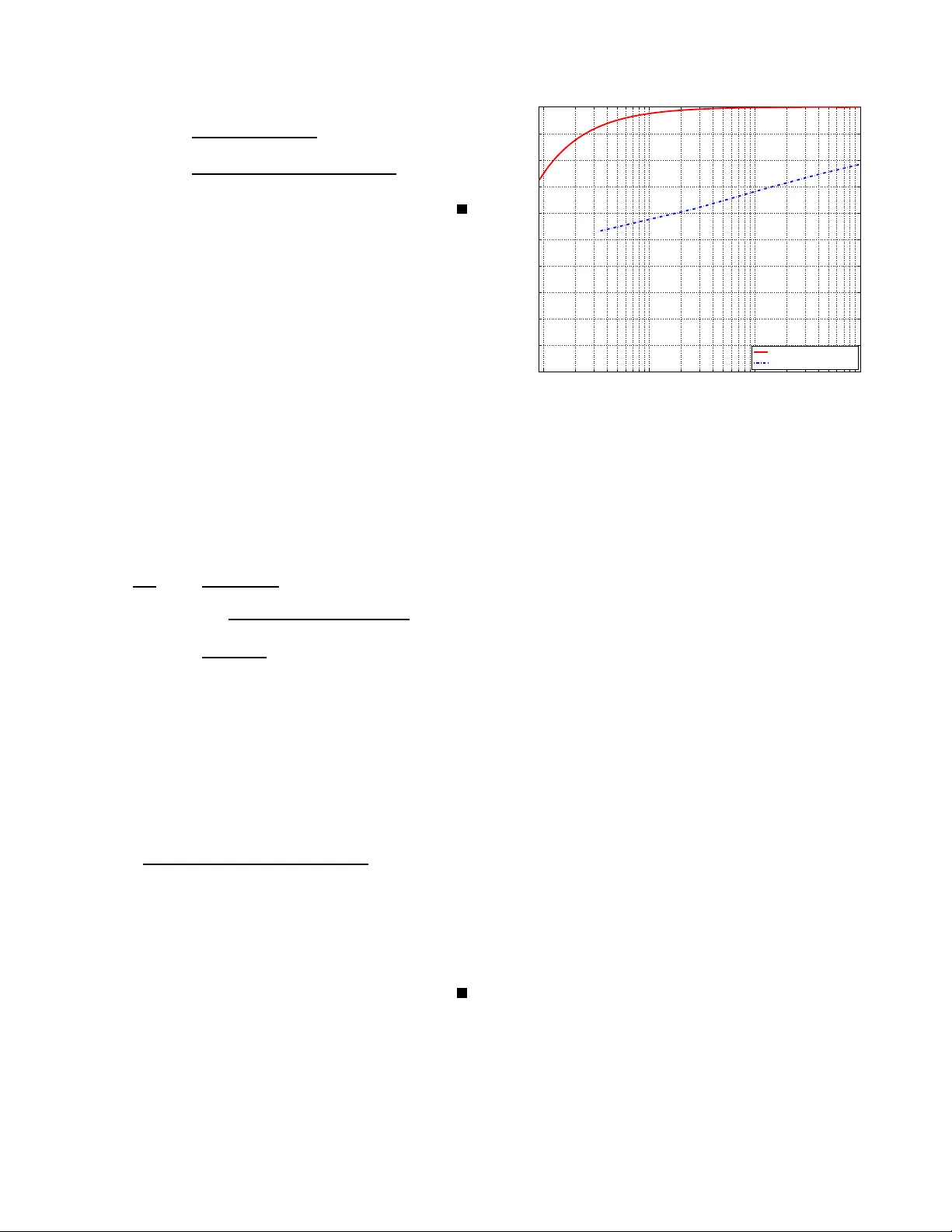
1 On the Beamforming Design for Ef ficient Interfere nce Alignment Sang W on Choi, Student Member , IEEE , S yed A. Jafar , Memb er , IEEE , and Sa e-Y oung Chu ng, Senior Membe r , IEEE Abstract —An efficient interference alignment (IA) scheme is deve loped for K -u ser single-input single-output frequency selectiv e fading in terference channels. The main idea is to steer the transmit beamforming matrices such that at each recei ver the su bspace dimensions occupied by interference-fr ee desired streams are asymptotically the same as those occupi ed by all interferences. Our proposed scheme achieves a h igher multiplexing gain at any giv en n umber of channel realizations in comparison with the original IA scheme, which is k nown to achiev e the optimal mu ltiplexing gain asymptotically . I . I N T RO D U C T I O N As an effecti ve technique for interferen ce managemen t, interferen ce alignm ent (IA) 1 has been pr oposed to achieve the o ptimal m ultiplexing gain asym ptotically in single-input single-outp ut (SISO) multi-u ser fadin g interf erence c hannel (IC) [ 2]. Sub sequently , the IA sche me h as been furthe r studied in an explicit mann er , which can b e classified into two categories: One is to achieve the IA in signal scale [ 3]- [5]. Specifically , multi-user interfere nces at each r eceiv er are aligned based o n carefully constructed signal structures. The other is to align in terferences in signal space [6], [7]. In this approa ch, transmit beamfor ming techniq ue is used to alig n th e multi-user interferences, which are nullified by ze ro-for cing (ZF) at each receiver . The main contribution of this paper is to propose an ef ficien t IA sche me in signal space wh en th e nu mber of users is greater than or eq ual to 3 . Specifically , we pr opose a tran smit b eam- forming design criterion so that a strictly higher multiplexing gain is attain ed in compar ison with the o riginal IA scheme [ 2] at any given numb er of channel realizations. I I . S Y S T E M M O D E L W e consider the f ollowing channel model: Y [ k ] = K X l =1 H [ kl ] X [ l ] + Z [ k ] , ∀ k ∈ K = { 1 , 2 , · · · , K } , (1) where M is the n umber of av ailab le frequ ency selectiv e channel realizations, Y [ k ] ∈ C M ( X [ l ] ∈ C M ) is the receiv ed (transmitted) signal vector of size M × 1 at the k -th receiv er (transmitter), and H [ kl ] ∈ C M × M is the M × M diago nal channel matrix from the l - th tran smitter to the k -th receiver . Here, the ( i, i ) -th compon ent h [ kl ] ( i ) of the c hannel matrix H [ kl ] is the ch annel coefficient in the i -th fre quency channel realization. W e assume the cha nnel is n ot time-varying . The noise vector Z [ k ] ∈ C M is complex Gau ssian with zero mean 1 The first implicit IA scheme has bee n studi ed in [1]. and the cov ariance of I M , wher e I M is the identity matrix of size M × M . W e assume the following in this paper . • All transmitters and receivers are equip ped with a single antenna. • All H [ kl ] ’ s are known in advance at all the tr ansmitters and all th e r eceivers. • The message of the i -th transmitter is indepen dent from that of the j -th transmitter , ∀ i, j ∈ K with i 6 = j . • All diago nal compo nents o f H [ kl ] ’ s ar e drawn indepen - dent and id entically distributed (i.i.d.) fro m a co ntinuou s distribution, and abso lute v alues of all diagon al elemen ts are bo unded below by a non zero minimu m value and above by a finite maximu m value. Remark 1: In SISO f requen cy selective fading IC, it is possible to use multiple fr equency selecti ve channel instances in a co mbined man ner, which leads to d iagonal c hannel matrices H [ kl ] ’ s, ∀ k, l ∈ K . The m ultiplexing gain r [8] of the K -user IC is defined as r = lim SNR →∞ R + ( SNR ) log( SNR ) , (2) where R + ( SNR ) is an achiev able sum- rate 2 at signal-to-n oise ratio (SNR), where SNR is defined as th e total power across all transmitters. I I I . P R E L I M I N A R I E S The essence o f the I A scheme lies in desig n of transmit beamfor ming ma trices. Basically , interferen ces are align ed at e ach receiver using the designed beamfor ming matrices to maximize the to tal num ber of in terferen ce-free desired streams. In the o riginal IA sch eme, the f ollowing IA co nditions wer e propo sed [2]. H [1 i ] V [ i ] = H [13] V [3] , ∀ i ∈ K \{ 1 , 3 } (3) and H [ j k ] V [ k ] ≺ H [ j 1] V [1] , ∀ j ∈ K \{ 1 , k } , ∀ k ∈ K \{ 1 } , (4) where V [ k ] is a M × d [ k ] transmit beamf orming matrix of the k -th user . Here, d [ k ] is the num ber of streams of the k -th u ser . Note that in ( 1 ) we h av e X [ k ] = V [ k ] S [ k ] , (5) 2 The definit ions of achie vable rate and ca pacity region follo w from [2], which is omitted due to space limitations. 2 T ABLE I I N T E R F E R E N C E AL I G N M E N T C O N D I T I O N S The first Rx. The second Rx. The k -th Rx. ( i ∈ K \{ 1 , 3 } ) k ∈ K \{ 1 , 2 } V [ i ] = H [1 i ] − 1 H [13] T [2] 3 V [3] ≺ V [1] , T [ k ] 2 V [3] ≺ V [1] , · V [3] . T [2] 4 V [3] ≺ V [1] , T [ k ] 3 V [3] ≺ V [1] , . . . . . . T [2] K V [3] ≺ V [1] . T [ k ] k − 1 V [3] ≺ V [1] , T [ k ] k +1 V [3] ≺ V [1] , T [ k ] k +2 V [3] ≺ V [1] , . . . T [ k ] K V [3] ≺ V [1] . where S [ k ] is a d [ k ] × 1 vector of streams, and A ≺ B means that the co lumn space o f A is included in tha t of B . Note that ( 3 ) means that all the inter ferences are align ed exactly to occupy the same su bspace at receiver 1 , while ( 4 ) implies that the subspace spanned by the first transmitter’ s interferen ces in cludes all the subspaces spanned by all the other transmitters’ inter ferences. W e define T [ k ] j ’ s as T [ k ] j = H [ k 1] − 1 H [ kj ] H [1 j ] − 1 H [13] , ∀ j, k ∈ K \{ 1 } (6) with j 6 = k . Then , the IA cond itions ( 3 ) and ( 4 ) are equiv a- lently rewritten as in T ABLE I . No te that with proba bility 1 all T [ k ] j ’ s ar e f ull-rank and T [ b ] a 6 = T [ d ] c for a 6 = c or b 6 = d since all the ch annel coefficients are assumed to be d rawn i.i.d. from a con tinuou s distribution. Suppose that there exist V [ k ] ’ s ( ∀ k ∈ K ) satisfying the IA condition s in T ABLE I, where the numb er of column vector s in V [ k ] is d [ k ] . When ea ch transmitter tra nsmits streams using the co rrespon ding transmit beamfor ming matrix V [ k ] and each receiver de codes the desired streams by ZF , the multiplexing gain r becomes r = ( K − 1) d [3] + d [1] d [3] + d [1] , (7) where d [2] = d [3] = · · · = d [ K − 1] < d [1] from ( 3 ) and ( 4 ) . Remark 2: When d [1] /d [3] approa ches 1 , ( 7 ) becomes close to the upper boun d of K/ 2 on the optimal multiplexing gain [2], [9]. Remark 3: Note that at the k -th receiver ( ∀ k ∈ K ) the ZF is po ssible d ue to the fact that effecti ve channel matrix of size ( d [3] + d [1] ) × ( d [3] + d [1] ) is full-rank with probab ility 1 [2 ], whe re the effecti ve ch annel matrix is formed b y the channel m atrices H [ kl ] ’ s a nd b eamform ing m atrices V [ l ] ’ s, ∀ l = 1 , 2 , · · · , K . In this paper, we propo se an efficient beam forming design satisfying the IA cond itions in T ABLE I. I V . P RO P O S E D I N T E R F E R E N C E A L I G N M E N T S C H E M E W e p ropo se th e fo llowing b eamform ing design criterion for our IA scheme. Assume a no nnegative integer n ∗ is given, then we d efine the following: V [3] = T [2] 3 − 1 Y k, l ∈ K \{ 1 } , k 6 = l, ( k ,l ) 6 =(2 , 3) T [2] 3 − 1 T [ k ] l n kl · 1 M X k, l ∈ K \{ 1 } , k 6 = l, ( k,l ) 6 =(2 , 3) n kl ≤ n ∗ (8) and V [1] = Y k, l ∈ K \{ 1 } , k 6 = l, ( k ,l ) 6 =(2 , 3) T [2] 3 − 1 T [ k ] l n kl · 1 M X k, l ∈ K \{ 1 } , k 6 = l, ( k ,l ) 6 =(2 , 3) n kl ≤ n ∗ + 1 , (9) where n kl ’ s ar e non negativ e integers, and 1 M is the all on e vector of size M × 1 . Th e be amformin g design criterion in ( 8 ) and ( 9 ) comes f rom the fo llowing m otiv a tion: I t is reaso nable to co nstruct V [1] and V [3] such that d [1] /d [3] becomes clo se to 1 , which is confirmed f rom ( 7 ) . For this, we use the f ollowing strategy . First, each colum n of V [1] and V [3] has the form of multiplication of matrices T [2] 3 − 1 T [ k ] l ’ s with exponents n kl ’ s. Second, W e limit the sum of n kl ’ s to satisfy the IA condition s in T ABLE I. Note that co lumn space of the b eamfor ming matr ix V [1] in ( 9 ) alw ays in cludes all colu mn sp aces o f T [ k ] l V [3] ’ s, ∀ k, l ∈ K \{ 1 } with k 6 = l and o ther beamf orming matr ices V [ k ] ’ s ( ∀ k ∈ K \{ 1 , 3 } ) a re constru cted directly from V [3] using ( 3 ) . Thus, the I A con ditions in T ABLE I ar e satisfied b y following ( 8 ) and ( 9 ) . Theor em 1: When K ≥ 3 , the m ultiplexing gain of ( K − 1)( n ∗ + 1) + n ∗ + N + 1 2 n ∗ + N + 2 (10) is achiev able f or any non negativ e in teger n ∗ in the K -user SISO fading IC, where N = ( K − 1 )( K − 2) − 1 . Pr oof: It is sufficient to specify d [3] and d [1] to ge t the achievable mu ltiplexing gain from ( 7 ) . Su ppose that we follow the beam forming design criterio n in ( 8 ) and ( 9 ) , which satisfies the IA condition s in T ABLE I . Since the construction rule f or the b eamfor ming matrix V [3] is exactly the same as that fo r V [1] , it is enough to show the num ber d [3] of co lumn vectors in V [3] satisfying ( 8 ) . From basic com binatoric results [11], d [3] is easily d eriv ed to be d [3] = n ∗ X n =0 n + N − 1 N − 1 = n ∗ + N N . (11) Similarly , we get d [1] = n ∗ + N + 1 N . (12) 3 Finally , we o btain r = ( K − 1) + d [1] /d [3] 1 + d [1] /d [3] = ( K − 1)( n ∗ + 1) + n ∗ + N + 1 2 n ∗ + N + 2 , (13) which completes the proo f. Remark 4: In th e sense o f the h igh-SNR offset, the pro - posed IA sch eme can be improved by u sing a better vector instead of 1 M as in [10] while maintaining the same achie v- able multiplexing gain in T heorem 1. Remark 5: Note that th e propo sed V [3] and V [1] lead to full-rank effective chan nel matrices at each receiver ( with probab ility 1 ), wh ich can be shown u sing contradictio n in a similar man ner as in [2]. This is because all the chann el coefficients are drawn i.i.d. from a continuous distribution. Remark 6: As n ∗ tends to infin ity , the optimal m ultiplexing gain of K / 2 is achieved asymptotically since d [1] /d [3] tends to 1 fr om ( 11 ) and ( 12 ) . Remark 7: In [ 2], the ratio d [1] /d [3] has been shown to be ( m + 2 ) N / ( m + 1 ) N for a n onnegative integer m , which correspo nds to the case when M = ( m + 1) N + ( m + 2) N in ( 1 ) . Given the fixed n umber of channel r ealizations, i.e., M = ( m + 1) N + ( m + 2) N = 2 n ∗ + N + 2 , the ratio d [1] /d [3] coming from the prop osed beam forming design satisfies d [1] d [3] = n ∗ + N + 1 n ∗ + 1 = 1 + 2 N ( m + 1) N + ( m + 2) N − N ≤ ( m + 2) N ( m + 1) N , (14) where the e quality ho lds iff N = 1 , which is equivalent to K = 3 . Remark 8: The propo sed bea mformin g design criter ion in ( 8 ) and ( 9 ) is mor e e fficient than the original one [2] wh en K ≥ 4 since beamf orming matrice s are design ed such th at d [1] /d [3] becomes closer to 1 while satisfying the IA conditions ( 3 ) and ( 4 ) , which is shown fro m ( 14 ) . Cor ollary 1: When K ≥ 3 , th e multiplexing gain of ( K M − 1)( n ∗ + 1) + n ∗ + N ′ + 1 2 n ∗ + N ′ + 2 (15) is achiev able in a fading IC with K transmitters and K receivers equipped with M anten nas each. Here, N ′ = ( K M − 1)( K M − 2) − 1 . Pr oof: It fo llows directly from Theo r em 1 by interpreting K -user fading IC with M an tennas as K M -user fading IC with a s ingle antenna. V . N U M E R I C A L R E S U LT S In Fig. 1, the achiev able multiplexing gains are shown for the prop osed IA scheme and for the orig inal one when K = 4 . I t is ob served that for each nu mber of chan nel uses, the propo sed one attains a strictly higher multiplexing gain th an the original o ne. No te that this becom es more significant as K increases beyond 3 . 10 1 10 2 10 3 10 4 0 0.2 0.4 0.6 0.8 1 1.2 1.4 1.6 1.8 2 Number of channel uses Multiplexing gain Proposed IA scheme Original IA scheme Fig. 1. Achie vable multiplex ing ga ins of the proposed IA scheme and the origina l IA scheme [2 ] when K = 4 . R E F E R E N C E S [1] M. Maddah-Ali, A . Motahari , and A. Khandani, “Signaling ov er MIMO multi-ba se systems - combi nation of multi-a ccess and broad cast schemes, ” in Pro c. IEEE Int. Symp. Inform. Theory , 2006. [2] V . R. Cadambe and S. A. Jafar , “Interfere nce alignme nt and the degrees of freedom for the K user interferen ce channel, ” IEEE Tr ans. Inf. Theory , vol. IT -54, no. 8, pp. 3425-3441, Aug. 2008. [3] V . R. Cadambe, S. A. Jaf ar , and S. Shamai (Shitz), “Interferenc e al ign- ment on the deterministi c channel and application to fully connecte d A WGN inte rference networks, ” IEEE T rans. Inf . Theory , vol. IT -55, no. 1, pp. 269-274, Jan. 2009. [4] S. Sridharan, A. Jafari an, S. V ishwa nath, S. A. Jafar , and S. Shamai (Shitz), “ A layere d lattice coding scheme for a cla ss of three use r Gaussian interfe rence chan nels, ” preprint. [5] R. Etkin and E. Ordentlich, “ On the degrees-of-fr eedom of the K -user Gaussian interference channe l, ” prepri nt. [6] K. Gomadam, V . R. Cadambe, and S. A. Jafar , “ Approachi ng the capacit y of wireless netw orks through distrib uted interfere nce alignment, ” preprint. [7] T . Gou and S. A. Jaf ar , “Degree s of freedom of the K user M × N MIMO interfe rence channel , ” preprint . [8] L. Zheng and D. N. C. Tse, “Div ersity and multiple xing: A fundamenta l tradeof f in multiple-ant enna channels, ” IEEE Tr ans. Inf. Theory , v ol. 49. no. 5, pp. 1073-1096, May 2003. [9] A. H ø st-Madsen and A. Nosratini a, “The multi plex ing ga in of wireless netw orks, ” in Pr oc. IEE E Int. Symp. Inform. Theory , 2005. [10] M. Shen, A. H ø st-Madsen, and J . V idal, “ An improv ed inter ference alignmen t scheme for frequenc y sel ecti ve cha nnels, ” in Pr oc. IEEE Int. Symp. Inform. Theory , 2008. [11] J. H. van Lint and R. M. W ilson, A course in combinato rics, Cambridge uni v . press, 1992.
Original Paper
Loading high-quality paper...
Comments & Academic Discussion
Loading comments...
Leave a Comment