Allocation of control and data channels for Large-Scale Wireless Sensor Networks
Both IEEE 802.15.4 and 802.15.4a standards allow for dynamic channel allocation and use of multiple channels available at their physical layers but its MAC protocols are designed only for single channel. Also, sensor's transceivers such as CC2420 pro…
Authors: Jamila Ben Slimane (INRIA Lorraine - Loria, Mediatron), Ye-Qiong Song (INRIA Lorraine - Loria
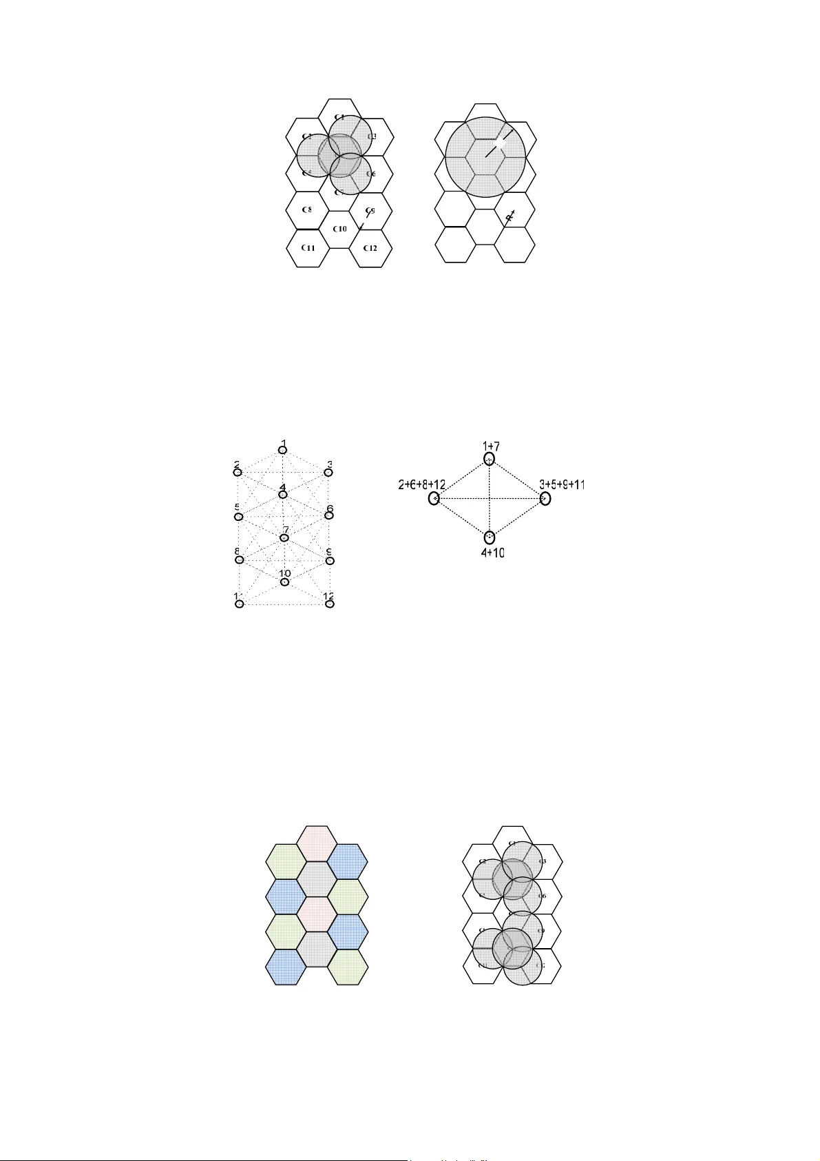
Allocation of control and data channels for Large-Scale Wireless Sensor Networks Jamila BEN SLIMANE 1,2 , Ye-Qion g SONG 2 , Anis KOUB AA 3,4 , Mounir F RIKHA 1 1 Sup'Com-MEDI ATRON, Ci ty of Co mmunication T echnologies, 2 083 Ariana, T unisia 2 LORIA and INP L, Campu s Scientifique, B P 239 54506 Vandoeuvre-les-Na ncy, France 3 IPP-HURR AY! Research Gr oup, P olytechnic Institute o f Po rto, Rua António Bernard ino de Almeida, 431, 4200 -072 Porto, Portugal 4 Al-Imam Muham mad ibn Saud University, Co mputer Science De pt.,11 681 Riyadh, Saudi Arabia Email: ja milabs07@yahoo. fr , Song@loria.fr , ako ubaa@dei.i sep.ipp .pt , m.frikha@supco m.rnu.tn I – Introduction Both I EEE 802.15.4 and 802.15. 4a standar ds allo w for d ynamic cha nnel alloc ation and use o f multiple channels available at their physical layers but its MAC protoco ls are designed only for single channel. Also, sensor's transceivers s uch as CC2420 provide multiple channels and a s shown in [1], [2] and [3] channel switc h latenc y of CC2420 tr ansceiver is j ust about 20 0µs. In order to enhance both ener gy efficienc y and to shorten end to end dela y, w e pr opose, in this report, a spectrum-efficie nt frequency allocation sche mes that are able to st atically assi gn control channels and dynamically reu se data cha nnels for P ersonal Area Net work s (PANs) insid e a Large- Scale W SN based o n UW B technology. II - System Model II - 1 - Netw ork Topology In ord er to d eploy a d ense network supp orting a c onsiderab le n umber o f nodes, we pro posed in [4] a three -tiered network to repre sent t he global net work, using UWB sensors in the first and second network level s. The choice of the UWB technolog y i s do ne to b enefit from it s extre me low tra nsmit p ower minimizing interference, high data rate allo wing re al time a nd high data rate ap plications and location capacit y allowin g mobilit y manageme nt and node identi fication. For the third tier , we prop ose W ifi network to b enefit fro m its high data rate, large coverage and security aspect. W hat we ai m is an application in hospital where the globa l net work r epresents WHSN (W ireless Hospital Se nsor Net work). Fig.1 sho ws all network la yers co mposing the W HSN. Fig.1 WHSN arc hitecture The lo west level rep resents the Bod y Sensor N etwork ( BSN). W e can model an e lementar y BSN b y a star network compo sed of o ne coo rdinator and a set o f bios ensors that e nsure ph ysiological m easure ments and medical moni toring o f patient . T o improve p atient's net work p erformance i n a dense hospital en vironment, we propose overla ying the net work of B SNs with a second up per level net work. T he hexago n cell repr esents the Personal Area Ne twork (P AN) or the second networ k level. As shown in Fig.1, the net work is represen ted by a cell of se nsors o rganized in mesh topo logy includi ng one PAN coo rdinator, several mo bile B SNs coord inators (one coord inator per BSN) and several routers. For an efficient solutio n for c hannel alloca tion a nd mobility management i n WHSNs, that cellular architec ture, based on UW B/Wifi tec hnologies, is c hosen to t he third level to have at the end a three-tier hierarchical cell ular net work. The d etailed descriptio n of the network architecture is o ut of sco op o f this report, so for more details, one ca n refer to [4 ]. In this p aper we are interested in UW B spectru m allocatio n prob lem at WHS N's second level (P AN). The problem o f freq uency allocatio n for WSNs is different fro m that treated in traditiona l cellula r networ k s uch GSM although we prop ose hexagonal cell ular repre sentation for the global net work seen that e ach net work have its proper specificity and r equirements. Let us a ssume the general case of a network co mposed b y of c N PANs or hexagonal c ells u nifor mly di stributed as shown i n Fig.2. T he ideal case of a hexagonal model is c hosen to e nsure t he totalit y coverage o f the net work. Although in practice the coverage zone of a sensor device is not a n hexagon or a perfect circle, there are proced ures and mechani sms [5] that ensure the adjustments of the model d uring network deployment b y means of experimental te st of meas ure ments. Let H be a Carte sian co ordinate system with 0, 0 C as origin po int with co ordinates ( ) 0 0 , x y , X for abscissa and Y for ordinate. We represent an arbitrar y cell center as , i j C by its coo rdinates ( ) , i j x y given by: [ ] 0 3 , ; 2 i R x x i i N N = + × ∈ − (1) [ ] 0 3 , ; 2 j R y y j j N N = + × ∈ − (2) ( ) mod 2 0 i j + = (3) [ ] { } 2 ( ( , ) /( , ) ; i j c Card x y i j N N N ∈ − = (4) Let C the set of all , i j C with coor dinates ( ) , i j x y verifying (1 ) to (4 ) as shown in Fig.2. Fig.2 General case o f a networ k of c N PANs In the follo wing sections only w e are interested in t he proble m of UWB-chan nels sharing between PANs, seen that the pro blem of Wifi-chan nels sharing within a mesh net work is alread y treated in [8 ] and [9 ]. II - 2 - IEEE 8 02.15.4 a IR-UWB SPECTRU M R ESOURCE IEEE 80 2.15.4a IR UWB complaint device s can op erate in three ind ependent ba nds: ( 1) the sub -gigahertz band (250-75 0 MHz), (2) the lo w band (3.1-5 GHz) and (3) th e h igh ba nd (6 -10.6 GHz). Fig.3 give s t he center frequencies and band widths of the admi ssible ba nds, as well as the reg ulatory domains in which the y are admissible. As shown i n the table 39 d give n in [6], we d ispose o f 16 ph ysical frequency cha nnels ass ociated with 8 seq uence codes to have in total 32 lo gical channel s. Fig.3 IEEE 8 02.15. 4a UWB plan bands According to tab le 39d given in [6] and Fig.3, neither o verlap ping c hannels nor ad jacent channels share same sequence code. Consequently, o verlapping channels d on't repre sent c o-channels since its seque nce codes ar e different, in this ca se, the simultaneous use (in clo se spa ce) of two o verlapping c hannels don't pro duce co - channel interfere nce. Also, ad jacent logical c hannels don 't interfere since its seq uence code s are different. Let us assume that tch N represents the set of total availab le log ical channels. Con forming to worldwide UW B regulation ( ) tch Card N is equal to 32 , 18 and 22 for respectivel y US, Europe and Japan region. According to rad io tran sceiver characteristics, channel switch latency does not exceed 2 00µs. Although we can assume that d uring one d uty cycle t he additional delay intro duced b y switchin g r adio cha nnels is not significant, but an efficient chan nel-switch protocol mu st be proposed to avoid unn ece ssary ch an nel switche s that can degrade the network p erfor mance. To switch from a cha nnel to another we need just to firstl y progra mme the set of available freque ncy cha nnels at t he leve l of a specific register ( e.g. FSCTRL.FREQ for CC2420 transceiver) then set this register to the ade quate val ue to select de manded channel. III - STATIC CHANNELS ALLOCATION III - 1 - ALLOCA TION OF CONTROL CH ANNELS III - 1 - a - Case of n etwork composed of 12 cells To avoid control channel congestion, we prop ose a static allocation of a n opti mal number of contro l channels. We assign o ne control cha nnel to each PAN to per sistently cover its cell fro m co ntrol tra ffic. We note t hat the overlapping channels (4 , 7, 11 and 15) are more suitable to ensure the co verage of suc h traffic since they are characterized b y its high band width [6] allo wing higher trans mit p ower per mitting a n exte nded range compared to non-overlapp ing channels. Notations. • c N : The tota l number of cells, • R : Radius of a c ell, • c c N x N D : Distance matrix, distance sep arating eac h couple of cell ce ntres, • cch N : Set of available co ntrol c hannels that repr esents a sub set of total contro l channel set tcch N . 7 7 7 7 cch tcch 8 8 8 8 (4, SC ), ( 7, SC ), (11, SC ), (15, SC ), N N = (4, SC ), (7, SC ), (11, SC ) , (15, SC ) ⊆ The rad ius of different cells is the sa me and eq uals to t he PAN co ordinator coverage zon e that we assu me be circular with r adius R and all PAN members transmi t with the same po wer transmit 0 P . The choic e of 0 P is done by taking into acco unt the foll owing equatio n. Rx 0 Rx P = P + Pl(R) / P - Link_margin = Rx_sen sitivity (5) Pathloss expres sion is give n in the 802 .15.4a standard [6]. So, in this c ase all PAN's members precisel y P AN member s lo cated at o r near the cell b order can hear their P AN coord inator co ntrol traffic (b eacon fra me,….), and it ca n be heard by their PAN co ordinator . W e can for mulate this pro blem a s 2-hop colo ring pr oble m, in which rep etition of colors occurs only if the nod es b elonging to different PANs a re separa ted by more tha n 2 hops. Consequentl y, as shown in Fi g.4 the minimum distance of fr equency r euse must b e strictly bigger tha n 2 hop s or distance c R (worst case). Let min D represents the minimal di stance of freque ncy r euse referrin g t o cells centers or po sitions of PANs coo rdinators: min c D > R (6) With c R is given b y: 2 c R R = (7) From (6) and (7) and according to networ k hexago nal representatio n, the s hortest dista nce frequency reuse a t cells centers will be: 3 4 ( ) ( 2 3 ) 2 min D = R R = (8) R a. C5 C7 C8 C10 C9 C4 C6 C12 C3 C1 C2 C11 Rc b. Fig.4 Radio co verage limit o f a logical c ontrol channel In this part, we are interested to find the mi nimal or op timal number o f logical co ntrol cha nnels cch opt N − ensuring a complete net work coverage taking into acc ount frequency reuse. This problem ca n be modelled as graph coloring pro blem "vertex colo ring". As sho wn in Fig.6 we can rep resent our net work as a ( , ) G V E graph, where: • Each cell center re presents a v ertex: V . • Distance separating t wo cells centers t hat is shorter than min D represents edge: E . Fig.5 Logical contro l channel allocatio n graph According to Fig.4 no t wo ce lls near than min D share t he same control c hannel. For that we c an call for one o f optimal coloring algorit hms su ch as Zykov's algorithm, branch and bo und m ethod, etc. The application of Zykov's algorith m to previous graph pro duces nine sub grap hs. In step 9, we are left with a co mplete graph ( "A co mplete grap h with n vertices o bviously r equires n colors" [7]). The optimal sol ution is given by the co mplete grap h with 4 vertices i n which vertice s 1 and 7 are allo cated to the first color , 2, 6, 8 and 12 to th e second co lor 3, 5 , 9 a nd 11 to the third color and vertice s 4 and 10 to the fourt h. We note that to c over the entire network by co ntrol tr affic without su ffering from co -channel interference, we just need of 4 different chan nel frequencies ( See Fig.6 a and Fig.6 b) Fig.6 Logical contro l channel allocatio n a. First step. b. Step9 : Merging of vertices (1+7 ), (4+10 ), (2+6+8+12), (3+5+9+11). CCH3 CCH1 CCH2 CCH4 CCH3 CCH4 CCH2 CCH2 CCH3 CCH1 CCH2 CCH3 a.Colors and c hannels allocati on. b. No co-channel inter ference. III - 1 - b - General case Theorem1 Given a WSN composed b y c N cells of radius R , to totally cov er it by co ntrol tr affic with one control channel per cell without suffering fro m co-channel i nterference, we need at most of 4 dif ferent channel frequencies. Proof1 We can disting uish the follo wing cases: • Case 1 c N = : The number of needed co ntrol channel s is equal to 1, • Case Number of adj acent cells = 2: Let and i, j m,n C C be t wo adj acent cell s (e. g. d| | < i, j m,n min C ,C D ) ⇒ the n umber of needed co ntrol channels is equal to 2, • Case Number of adj acent cells = 3: Let and i, j m ,n k, l C , C C b e three ad jacent cells (e.g. d| | = d| |= d| |< i, j m,n i, j k,l k, l m ,n min C ,C C ,C C ,C D ) ⇒ the number of needed control cha nnels is eq ual to 3, • Case Number of adj acent cells 4 ≥ : According to the e xample o f 12 ce lls net work, the shor test distance frequency re use min D for control chan nels is equal to ( 2 3 ) R . So to use the same freq uency for a given couple of cells ( ) i, j m,n C ,C C ⊂ , the d istance separating the t wo cells must be equal to or bigger than min D ( ) ( ) ( ) ( ) ( ) ( ) , , 2 2 2 2 2 2 2 2 0 0 0 0 2 d , ( 2 3 ) 12 3 3 3 3 12 2 2 2 2 3 3 2 2 i j m n min i m j n i m j n C C D x x y y R x x y y R R R R R x i x m y j y n R R R i m j n ≥ − + − ≥ − + − ≥ + × − + × + + × − + × ≥ × − + × − ( ) ( ) 2 2 2 2 12 3 1 6 R i m j n ≥ × − + − ≥ (9) Let sub sets ij E , ij F and ij G given as follo ws: ( ) ( ) , 2 2 / 3 16 m n ij ij C C E i m j n and fixed C C ∈ = × − + − > ∈ , ( ) ( ) , 2 2 / 3 16 m n ij ij C C F i m j n and fixed C C ∈ = × − + − = ∈ and { } ij i j ij G C E F = − ∪ You can re write ij F as: ( ) ( ) 2 2 3 16 i m j n × − + − = ⇒ ( ) ( ) ( ) ( ) 2 2 2 2 4, 4 2, 0, 16 , 4 i m j n i m j n i m j n i m j n − = − = ⇒ − = − = − = − = ⇒ = − = (10) Without loss of generalit y we can resolve ( 10) by co nsidering simple case of 00 F then we deduce a general solution for ij F C ∀ ⊂ . According to the d efinition of ij F , , 00 m n C F ⊂ : 04 22 2 2 , 0 4 2 2 22 , , , , m n C C C C C C C − − − − − ∈ So, as shown in F ig.8, we can deduct 00 G from 00 F . Fig.7 Graphic rep resentation o f 00 F and 00 G sets Consequentl y, / i, j m,n ij (i, j) C C, C F ∀ ∈ ∈ 4 2 2 2 2 , 4 2 2 2 2 , , , , , ij i j i j m n ij i j i j C C C C C C C + + + + − − − − − + = So, ( ) ( ) , , / , , i j m n ij ij mn C C and C G i j m n CCH CCH ∀ ∈ ∀ ∈ ≠ ⇒ ≠ (11) ( ) , , , , / i j m n m n ij ij mn C C C C G CCH CCH ∃ ∈ ∉ ⇒ = (12) According to (11) , (12) and Fig.8 w e can work into a give n set ij G then we ge neralize the result for the entire network C . Taking for exa mple t he sub net work 24 G . Let 1 CCH be a llocated to c ell 2, 4 C , in t his ca se ( ) , 24 /( , ) 2, 4 m n C G m n ∀ ∈ ≠ must not use t he channel 1 CCH . Let ( ) 24 , G V E be the graph of sub net work 24 G . The application of Zykov 's a lgorithm to ( ) 24 , G V E produces nine s ub graphs a s the ca se of 1 2 cells. In final p hase ( 9 th step) , we are left with a complete graph with 4 vertices. The opti mal solution is given b y the co mplete graph in which verte x 2, 4 C is a llocated to t he first color , 1, 1 1,5 3,3 ,C ,C C and 3, 7 C to the second co lor and 2,2 2, 6 0,4 4,4 C , C , C C to the third colo r and vertices and 1,3 1, 7 3, 1 3,5 C , C , C C to the fourth. To generalize this res ult you c an appl y the same pro cedure to all sub net works ij G C ⊂ . Fig. 8 Grap hic repr esentation o f ij E , ij F and ij G sets III - 1 - DATA CH ANNE LS III - 1 - a - Case of n etwork composed of 12 cells For data communication, we pro pose the use of the non overlapp ing channels ( 0, 1, 2, 3, 5, 6, 8, 9, 10, 1 2, 13 and 14) and the supplementar y overlapp ing channels with t heir ap propriate sequence code. Notations. • c N : the total nu mber of cells with radius R , • c c N xN D distance matrix, dis tance separ ating each co uple of cell ce ntres • tch N : set of total cha nnels, • tdch N : set of total d ata co mmunication channels, • dch N : set of avai lable data communication cha nnels, it represe nts a s ub set o f total data co mmunication channels set tdch N . tdch tch cch N = N N − dch tdch N N ⊆ According to worldwide UW B regulations: o For US re gulation : dch tdch N N = , ( ) ( ) 28 dch tdch Card N Card N = = , o For Europ ean regulation : dch tdch N N ⊂ , ( ) 1 4 dch Card N = , o For Ja pan’s regulation : dch tdch N N ⊂ , ( ) 20 dch Card N = , For da ta communication, we assu me t hat all P AN me mbers transmit with the same tr ansmitter power 1 P , in order to have a coverage of ra dius r . 2 R r < (13) In order t o ensure efficient energy management, w e propo se a multi-hop ro uting i nside each ce ll which is structured in mesh topolo gy. One hop must b e equal to o r shorter than $r $ in orde r to: • d ecrease trans mit power to sa ve sensor ba ttery, maximize n etwork life time a nd avoid int erference, • b alance energy con sumption and load o ver all cells of the ne twork. The choice of 1 P is done b y taking into account the following equation. Rx 1 Rx P = P + Pl(r) / P - L ink_margin = Rx_sen sitivity (14) As s hown in Fig.11 taking t he exa mple o f cell n umber 4, P AN members e xcept PAN co ord inator can be lo cated at any position in side their cel l. So, we note for the c ase o f sensor s located at or near the c ell bor der that they c an inter fere with sensors of adjace nt PANs, located a t or near their cell bord er. a . Elementary cluster b. Control channel allocation for 24 G Fig. 9 Control c hannel allocati on a. Radio co verage limit of a se nsor b . Radio co verage limit of a P AN Fig.10 Radio c overage limit o f a logical da ta co mmunication channel Consequentl y, as shown in F ig.10 the mini mum distance of frequency re use must be strictl y big ger than c R (worst case). Let min ' D represents th e minimal distance of freque nc y reuse re ferring to cell s cente rs or positions of PANs coord inators: min c D' > R (15) With c R is given b y: c R R r = + (16 ) From (15) and ( 16) and acc ording to network he xagonal re presentation, the shortest dista nce frequency reu se at cells centers will be: 3 min D' = R (17) In this par t, we ar e intere sted to find the minimal number o f data co mmunication channels to cover the global network taking into acco unt frequenc y re use. Similar to the case of contro l channel allocatio n, this problem can be translated into graph colo ring prob lem ap plied to the graph sho wn b y Fig.11a s uch t hat no two adjace nt vertices sh are the same color. For that we can also call to Zykov's algor ithm. The application of Zykov's algorithm to the pr evious grap h prod uces ten sub graphs. In step 10, we are left with a complete graph. The optimal solution is given b y the complete grap h (Fig.11 b) with t hree vertices. W e note that to cover all the net work from communica tion traf fic without sufferin g fro m co - channel interfere nce, we j ust need of 3 different channel freq uencies (See Fi g.12 a a nd Fig.12 b). In the presen t case, the minimal nu mber of d ata co mmunications c hannels dch opt N − , to c over the totalit y of the network by one data channel p er P AN, is equal to three. Fig.11 Logical d ata co mmunication channe l allocation graph a. First step. b. Step10 - Merging ve rtices (1+5+6+10), (2+3+7+1 1+12), (4+8+9). Fig.12 Logical d ata co mmunication channe l allocation III - 2 - b - General case Theorem2 Given a WSN co mposed by c N cells of ra dius R organized o n mesh topolo gy with a node coverage eq uals to $r$, to tota lly cover the network b y data tr affic with one dat a channel per cell without suf fering fro m co-c hannel interference, we need at most of 3 d ifferent channel freque ncies. Proof2 • Case N umber of adj acent cells = 2: • Case N umber of adj acent cells = 3: Let and i, j m,n k, l C , C C b e three ad jacent cells (e.g. d| | = d| |= d| |< i, j m,n i, j k,l k, l m ,n min C , C C ,C C , C D ) ⇒ the number of needed control cha nnels is eq ual to 3, • Case N umber of adj acent cells 4 ≥ : We can disting uish the follo wing cases: • Case 1 c N = : The number of needed d ata channel is equal to 1, • Case N umber of adj acent cells = 2: Let and i, j m,n C C be t wo adj acent cells (e. g. d| | < ' i, j m,n min C , C D ) ⇒ the number of needed contro l chan nels is equal to 2, • Case N umber of adj acent cells 3 ≥ : For the case of da ta co mmunic ation, si milar to Pr oof1 done for control channel allocatio n (case o f adjace nt cells number 4 ≥ ), to allo w frequency r euse for a given co uple of cells { } i, j m,n C , C C ⊂ , the distance sepa rating th e two cells centers must be equa l to o r bigger than min ' D . ( ) ( ) ( ) ( ) ( ) ( ) , , 2 2 2 2 2 2 2 2 0 0 0 0 2 d , ' 3 9 3 3 3 3 9 2 2 2 2 3 3 2 2 i j m n min i m j n i m j n C C D x x y y R x x y y R R R R R x i x m y j y n R R R i m j n ≥ − + − ≥ − + − ≥ + × − + × + + × − + × ≥ × − + × − ( ) ( ) 2 2 2 2 9 3 12 R i m j n ≥ × − + − ≥ (18) Let sub sets ' ij E , ' ij F and ' ij G given as follo ws: a. Data communicatio n channels allo cation. b. No co-channel interference. ( ) ( ) , 2 2 ' / 3 12 m n ij ij C C E i m j n and fixed C C ∈ = × − + − > ∈ , ( ) ( ) , 2 2 ' / 3 12 m n ij ij C C F i m j n and fixed C C ∈ = × − + − = ∈ and { } ' ij i j ij G C E F = − ∪ You can re write ' ij F as ( ) ( ) ( ) ( ) ( ) ( ) 2 2 2 2 2 2 1 , 9 1 , 3 , 4, 0 2, 0, 1 , 3 1 , 3 3 12 1 , 3 1 , 3 2, 0 2, 0 i m j n i m j n i m j n i m j n i m j n i m j n i m j n i m j n i m j n i m j n i m j n − = − = ⇒ − = − = − = − = ⇒ − = − = = + = + = − = + × − + − = ⇒ = + = − ⇒ = − = − = + = = = − = = (19) As done in Pr oof1, we conclude that ( ) , , / i j i j C C ∀ ∈ , and i j i j F' G' can be re written as follo ws: = i - 1, j - 3 i +1, j - 3 i - 1, j+ 3 i j i+1, j+ 3 i - 2, j i+ 2, j C , C , C F' C , C , C 2 2 1 1 1 1 1 1 = i, j i, j i, j i+1, j + i - , j i , j i j i+1, j C , C , C C , C , C G' C + − − − + − So, ( ) ( ) ' , , / , , i j m n ij ij mn C C and C G i j m n DCH DCH ∀ ∈ ∀ ∈ ≠ ⇒ ≠ (20) ( ) ' , , , , / i j m n m n ij ij mn C C C C G DC H DCH ∃ ∈ ∉ ⇒ = (21) According to (20 ) and (21) , we can w ork into a fixed set i j G' then we generalize the result for the entire network C . Taking for example the sub network 24 G' , let 1 DCH be allocated to cell , 2 4 C , in t his case ( ) ' , 24 /( , ) 2, 4 m n C G m n ∀ ∈ ≠ must not use t he channel 1 DCH . Let ( ) ' 24 , G V E be the graph of ' 24 G . The app lication of Zykov's al gorith m to the p revious grap h pr oduces five sub graph s. In s tep 4, we are left with a complete grap h with 3 vertices. The o ptimal solution is given b y the co mplete grap h in which vertex 2, 4 C is allocated to the first color, and 1,3 2,6 3,3 C , C C to the second co lor 4 2 5 and 1, 2, 3, C ,C C to the third. 24 C 26 C 15 C 35 C 13 C 33 C 22 C a. Ele mentary cluster b. Control chan nel allocation i nside ' 24 G . Fig.13 Data cha nnel allocatio n To generalize th is result you c an appl y the same proced ure to all sub net works ij G' C ⊆ . IV - DYNAMIC DATA CHANNELS ALLOCATIO N IV - 1 - General case o f dynamic channel s allocat ion According to available c hannel frequenc ies dch N and PANs duty cycle, each PAN ca n benefit simultaneo usly from several da ta channels. We define K as : ( ) Div dch dch opt K ceil Card N N − = < K rep resents the number o f si multaneous data channel freq uencies that can be nefit eac h P AN. Fro m a spectr um regulation to anot her, K isn't the sa me, for US: 8 K = , Europe: 4 K = and Japan: 6 K = . But in rea lity eac h PAN is c haracterized by its d uty c ycle o r super frame duratio n, as shown in Fi g.14. So , according to P ANs duty cycle K can change duri ng global net work active p eriod. Let u s assume the ge neral case of a network co mposed by c N PAN coord inators with corre spondent superfra me durations { } 1 ( , ) c i i i i N PAN SD BI ≤ ≤ = . We define maj BI , min SD and U as respectivel y the major c ycle, the elementary acti ve cycle (ie e lementary time unit) and the nu mber of elementar y active c ycle per major cycle. Frame Beacon Frame Beacon SO SD = aBaseSuperfram eDuration * 2 symbo ls BO BI = aBa seSuperframeDurati on * 2 symbols Fig.14 PAN supe rframe struc ture 1 2 1 2 1 2 1 min 1 2 1 min ( , , ... ) (2 , 2 , ...2 ) max ( 2 ) ( , , ... ) ( 2 , 2 , ...2 ) min ( 2 ) N c i c c N c i c c BO BO BO BO maj N i N SO SO SO SO N i N maj BI LCM BI BI BI LCM SD LCD SD SD S D LCD BI U SD ≤ ≤ ≤ ≤ = = = = = = = Let c N xU DC and c c N xN D represent respectively the matri x of d uty cycle of all PANs coord inators per elementary acti ve cycle and th e matrix of dista nces separati ng each couple o f cells cen ter. 11 1 21 1 1 c c c U N xU N U N DC DC DC DC DC DC − = 1 21 1 1 1 0 0 0 0 c c c c c c N N xN N N N D D D D D − − = So, given c N xU DC , min D' and c c N xN D , we c an deter mine the graph ' ( , ) i G V E per ele mentary ac tive cycle an d then co mpute opti mal data communica tion cha nnels to cover the totalit y of the net work as d one in previou s section (the case where all P AN coo rdinators ar e active). In last step, we co mpute the numbe r o f simulta neous data communication channels i K per active PAN for the relative elementar y active c ycle. ( ) Div i dch dc h opt i K ceil Ca rd N N − = In conclusio n, con sidering the available data communicatio n channels dch N , c N xU DC , c c N xN D , min D' , we ca n compute the matrix of sub set of data co mmunication chann els per ce ll per elementar y active cycle. 11 1 21 1 1 U N xU c N U c N c dch dch dch dch dch dch N N N N N N − = For example 11 dch N represents the set of d ata communic ation chan nels used b y the first P AN (I D =1) duri ng the first elementar y active cycle, where 1 11 dch Card N K = . With JAV A pr ogramming lang uage (E clipse-SDK -3.4.1) and M ATLAB R2008a environment, pr oposed schemes ar e i mplemented. Fo r static allocatio n our algorith m pr esents a co mplexity o f o rder O(n) , where for dynamic allocation i t is less fa st and it present s a complexit y of order 2 O(n ) . IV - 2 - Performance evalua tion Let us consider a synchronize d UWB -based WHSN o f 12 PANs. T aking the exa mple of the worst c ase given b y Fig.15 where all P ANs begin communicatio n at the same ti me. Let us assume t hat the Europ ean regulation i s adopted (i.e. channels 4 and 7 for control and the rest for data). Each i PAN is characterized by its s uperframe d uration ( , ) i i SD BI as shown b y Fig.15. So, min min , , , , , 32 32, 1 , , 32 1 maj maj BI BI SD U SD = = = = = . Fig.15 Example o f PAN confi guration According to Fig.16 we note t hat: • Durin g the st nd th th 1 , 2 , 17 and 18 elementary cycles, each active PAN b enefit si multaneously from 4 channels. • Durin g the rd th th th 3 , 4 , 9 and 25 elementary cycles each active PAN bene fit fro m 7 cha nnels (co mplete graph is composed by two ver tices). • Durin g the th th th th th th 5 , 6 , 7 , 8 , 19 and 20 elementary cycle s, only one PAN rd th (3 or 11 ) is active which benefit si multaneousl y from all availab le channels. • Durin g the th t h 10 and 26 elementary c ycles o nly two P ANs th th (6 and 10 ) are a ctive, each one b enefit simultaneou sly from all a vailab le cha nnels bec ause the dis tance separating t hose two P ANs is greater than min D' . Fig.16 Data channels allo catio n during acti ve ele mentary c ycles As il lustrated i n F ig.17, with static data c hannels allocatio n, the maxi mum number o f alloc ated channels per PAN is 8, 6 and 4, respective ly for US, Japanese a nd E urop ean r egulation. Where with dynamic data c hannels allocation d uring speci fic ele mentary c ycles active PANs can bene fit fro m supple mentary cha nnels which a re initially been allo cated to some other P ANs. During t he th th th th t h th th th 5 , 6 , 7 , 8 , 10 , 19 , 20 and 26 active P ANs be nefit up to 28, 18 and 14 in r espectively US, Japanese and E uropean regula tion. Fig.17 Static vs D ynamic c hannel alloca tion Inside each ac tive PAN s and durin g each ele mentar y cycle, let us assume t he simple scenario o f hight reque sts of three time slots each one. At t he level of each active P AN coo rdinators, we suppose that re quests ar e scheduled without any con flict. According to Fig.18 and Fig.1 9 we note that: • W ith single data cha nnel and static multi -channel schemes, each active P AN needs respec tively 2 4 and 6 time slots to ans wer to all request s. Although with static multi-cha nnel scheme th e results are extremely better than with single data c hannel scheme but we note a spectr um resource waste during PANs sleep p eriod. Fig.18 Required Time slots i nside the rd th 3 and 11 PANs Fig.19 Per centage of dela y decrease o f the th 11 PAN • With d ynamic multi-c hannel sc heme we note : o To answ er to all requests, the rd th 3 and 11 PANs require only 4 tim e slots during rd t h 3 and 4 elementary cycles a nd 3 ti me slots during respe ctively th th (19 , 20 ) and th th th th (5 , 6 , 7 , 8 ) elementar y cycles. o In this way we can en sure, on the o ne ha nd, an e fficient and fair d ata c hannels a lloca tion between PANs per mitting a n enhance ment of QoS inside each P AN and, o n the o ther ha nd, a maximization o f cha nnel utilit y. V - CONCLUSION As pro nounced in t he be ginning o f t his pap er, e fficient allo cation of the availa ble spectrum r esource i n WSN s under scalab le and optimal multi-freq uency M AC pro tocols allowing par allel tra nsmissio ns with o pti mal u se of available r esource , without suffering from i nterfere nce, data co mmunication con flict and contro l pac ket overhead, seem to be an imper ative and c hallengin g task. To resolve such prob lem for l arge-sca le and dense WSNs as WHSNs, we p rop ose to d ecompose t he frequenc y allocation pr oble m into two sub-pr oblems: static co ntrol channel allocation to ensure a pe rmanent co ntrol frequency per PAN avoid ing control channe l co ngestion pr oblem and d ynamic d ata c hannel alloc ation b ased o n PANs duty c ycle infor mation and spatial fre quenc y reuse to avoid the u nderutiliza tion o f spectru m resource. Bibliogra phy [1] X. Chen, P .H. Qiu-Sheng, H. Shi-liang, T.Zhang-Lo ng, Chen , "A Mul ti-Channel MAC P rotoco l for Wireless Se nsor Net works", T he Sixth IEEE I nternatio nal Confere nce on Co mputer and I nformatio n Technolo gy, Seoul, Se ptembe r 20 06, pp. 224 -224. [2] X. W ang and T. Be rger, "Spatial cha nnel reuse in wireless sensor network s", W ireless N etworks Jo urnal, vol 14, iss 2 , pp. 1 33-146, M arch 2008 . [3] CC24 20 datasheet, 2004 chipcon,inst.ee cs.berkele y.edu/cs1 50/Do cuments/CC2 420. pdf [4] BS. Jamila, S. Ye -Qiong, K. Anis, F. Mo unir, "A Three-Tier ed Architecture for Large-Sca le Wireless Hospital Sen sor Net works", the Inter national Wo rksho p on Mob ilizing He alth Infor mation to Supp ort Healthcare -Related K nowledge Wor k - MobiHea lthInf 2009, p p 20-31 . [5] J . Jemai, R.Piesie wicz, T .Kurner, " Calibratio n of an i ndo or ra dio propagatio n pred iction model a t 2.4 G Hz b y measure ments o f the IEEE 8 02.1 1b p reamble" IEEE 6 1 st Vehicular T echnology Confere nce, Spr ing. 20 05,Vo l 1, pp.1 11-115. [6] I EEE 802. 15.4a Standar d Pa rt 15.4: I EEE Standard for I nformation T echnolo gy, Amend ment to IEEE Std 802. 15.4™-200 6, 2007. [7] A. Kathr yn, "Classica l T echniques", Springer US B ook, chap ter 2, 2005, pp .19-68. [8] B. Ra man, " Channel Alloc ation in 802 .11-B ased Mesh Networks", 25th IEEE I nternational Conference on Computer Communica tions, IN FOCOM 2 006 , pp. 1-10. [9] A.H.M . Rad, V. W.S. W ong, "Joint cha nnel alloc ation, inter face assign ment and M AC d esign for multi- channel wirele ss mes h networ ks", in Pr oceed ings of IEEE IN FOCOM, 2007 , pp. 1469 -1477 .
Original Paper
Loading high-quality paper...
Comments & Academic Discussion
Loading comments...
Leave a Comment