Methods are presented for measuring thrust using common force sensors and data acquisition to construct a dynamic force plate. A spreadsheet can be used to compute trajectory by integrating the equations of motion numerically. These techniques can be used in college physics courses, and have also been used with high school students concurrently enrolled in algebra 2.
Deep Dive into Measuring thrust and predicting trajectory in model rocketry.
Methods are presented for measuring thrust using common force sensors and data acquisition to construct a dynamic force plate. A spreadsheet can be used to compute trajectory by integrating the equations of motion numerically. These techniques can be used in college physics courses, and have also been used with high school students concurrently enrolled in algebra 2.
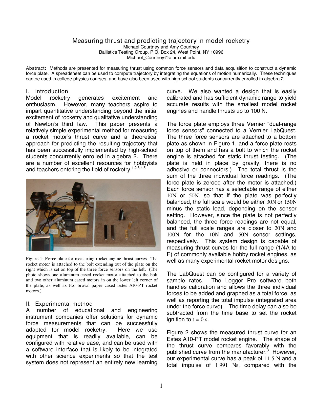
Model rocketry generates excitement and enthusiasm. However, many teachers aspire to impart quantitative understanding beyond the initial excitement of rocketry and qualitative understanding of Newton's third law. This paper presents a relatively simple experimental method for measuring a rocket motor's thrust curve and a theoretical approach for predicting the resulting trajectory that has been successfully implemented by high-school students concurrently enrolled in algebra 2. There are a number of excellent resources for hobbyists and teachers entering the field of rocketry. 1,2,3,4,5 Figure 1: Force plate for measuring rocket engine thrust curves. The rocket motor is attached to the bolt extending out of the plate on the right which is set on top of the three force sensors on the left. (The photo shows one aluminum cased rocket motor attached to the bolt and two other aluminum cased motors in on the lower left corner of the plate, as well as two brown paper cased Estes A10-PT rocket motors.)
A number of educational and engineering instrument companies offer solutions for dynamic force measurements that can be successfully adapted for model rocketry.
Here we use equipment that is readily available, can be configured with relative ease, and can be used with a software interface that is likely to be integrated with other science experiments so that the test system does not represent an entirely new learning curve. We also wanted a design that is easily calibrated and has sufficient dynamic range to yield accurate results with the smallest model rocket engines and handle thrusts up to 100 N.
The force plate employs three Vernier “dual-range force sensors” connected to a Vernier LabQuest. The three force sensors are attached to a bottom plate as shown in Figure 1, and a force plate rests on top of them and has a bolt to which the rocket engine is attached for static thrust testing. (The plate is held in place by gravity, there is no adhesive or connectors.) The total thrust is the sum of the three individual force readings. (The force plate is zeroed after the motor is attached.) Each force sensor has a selectable range of either 10N or 50N, so that if the plate was perfectly balanced, the full scale would be either 30N or 150N minus the static load, depending on the sensor setting. However, since the plate is not perfectly balanced, the three force readings are not equal, and the full scale ranges are closer to 20N and 100N for the 10N and 50N sensor settings, respectively. This system design is capable of measuring thrust curves for the full range (1/4A to E) of commonly available hobby rocket engines, as well as many experimental rocket motor designs.
The LabQuest can be configured for a variety of sample rates. The Logger Pro software both handles calibration and allows the three individual forces to be added and graphed as a total force, as well as reporting the total impulse (integrated area under the force curve). The time delay can also be subtracted from the time base to set the rocket ignition to t = 0 s.
Figure 2 shows the measured thrust curve for an Estes A10-PT model rocket engine. The shape of the thrust curve compares favorably with the published curve from the manufacturer. 6 However, our experimental curve has a peak of 11.5 N and a total impulse of 1.991 Ns, compared with the manufacturer’s claims of a peak thrust of 13.0 N and a total impulse of 2.5 Ns. The total impulse (area under total thrust curve) is 20% lower than the manufacturer’s claim. The bulk of this discrepancy is likely due to the engine containing 19% less (3.08 g) than the specified quantity (3.78 g) of propellant, since our measured specific impulse (impulse divided by propellant weight) is 64.64 s, which is only 4% lower than the manufacturer’s specification of 67.49 s for specific impulse.
(Measurements showing the A10-PT being below specification have been consistently repeated on different days using independent calibrations.) Figure 3 shows the measured thrust curve for an experimental motor with a sugar-based propellant containing a 65/35/2 blend of KNO 3 , C 6 H 12 O 6 , and Fe 2 O 3 . The theoretical specific impulse of this blend can be much higher (above 150 s) 7 but this motor’s operating pressure is relatively low because of the propellant’s slow burn rate and the motor’s relatively large nozzle size. Filled to capacity (10 g) with a sucrose-based propellant, we believe this reloadable Maglite-based motor can have a specific impulse close to 100 Ns.
Since the mass of the rocket is changing during the burn phase of flight, the acceleration is given by
, where V is the instantaneous velocity, and m is the mass.
Setting up the spreadsheet requires estimating the mass as a function of time. A linear interpolation between the initial and final masses can be used. Since the changing mass term and weight are much smaller than the thrust, and also smaller than the drag, there is only a small error from the li
…(Full text truncated)…
This content is AI-processed based on ArXiv data.