Cross-Layer Link Adaptation Design for Relay Channels with Cooperative ARQ Protocol
The cooperative automatic repeat request (C-ARQ) is a link layer relaying protocol which exploits the spatial diversity and allows the relay node to retransmit the source data packet to the destination, when the latter is unable to decode the source …
Authors: Morteza Mardani, Jalil S. Harsini, Farshad Lahouti
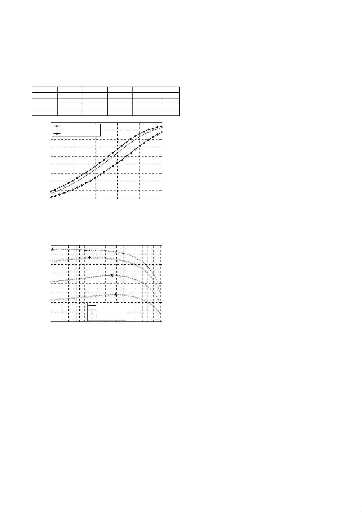
CROSS-LAYE R LINK AD APTATION DESIGN FO R RELAY CHANNE LS WITH COOPERATIV E ARQ PROTOC OL Morteza Mardani, Jalil S. Harsini and Farshad Lahouti Emails: m.mardan i@ece.ut.a c.ir, j.harsini@ece.ut.ac.i r, lahouti@ut.ac.ir WMC Lab., School of Electrica l and Computer En gineerin g, University o f Tehran ABSTRACT The cooperative autom atic repeat reque st (C-ARQ) is a link l ayer relaying protocol which exploits the spatial div ersity and allows the relay node to retransmit the source d ata packet to the destination, when the latter is unable to decode the source data correctly. This p aper presents a cross-lay er link adaptation d esign for C-ARQ based relay channels in which both source and relay nodes employ adaptive modulation coding and power adaptation at the phys ical laye r. For this scenario , we firs t derive cl osed-for m expressions for the system spectral efficiency and average power consumption. We then present a lo w com plexity iterative algorithm to find the optimized adaptation solution by m aximizing the spectral efficien cy subject to a packet loss r ate (PLR) and an average power consum ption constraint. The results indicate th at the proposed adaptation scheme enhances the spectral efficiency noticeably when comp ared to other adaptive schem es, while guaranteeing the required PLR performance. Index Terms — Relay channel, adaptiv e modulation coding, power adaptation, spectral eff iciency, cross-lay er design. 1. INTRODUCTION Recently, coope rative relaying h as emerged as a powerfu l spatial diversity technique for improved perf ormance over direct transmission. T he relay channel and th e associated practica l relaying protoco ls are extensiv ely studied in the liter ature, e.g., in [1]. The incremental decode-an d-forward (DF) and selectiv e DF relaying protocols are presented to achieve a higher spectral efficiency over the relay channel [1]. The coo perative autom atic repeat request (C-ARQ) is a link level relaying protocol, which exploits the benefits of both increm ental and selective DF relaying protocols [2-3]. This paper presen ts a cross-layer approach for lin k adaptation design over a relay ch annel employing C-ARQ protocol at the data-link l ayer. It is well known that link adaptation at the transm itter based on adaptive modulation and coding (AMC) and power control is a powerful technique to enhance the system spectral efficiency (SE) over time-varying fading channels [4-5]. To exploit th e benefits of power and rate adaptation ov er the relay channel, recently , several studies have bee n reported in th e literatur e, e.g., [ 6]-[8]. In [6] , the authors proposed a discrete rate and power adaptation policy for the DF relay channel, in which the source and relay transmit with the same power level and coding rate. They have shown that f or a finite-rate feedback, a higher thr oughput gain is achieved by us ing higher coding rates and allowing some outage probability for data transmission. A constant-power adaptive modulation schem e for a relay network taking advantage of increm ental amplify -and- forward (AF) relaying protocol is proposed in [7], where the selected relay forwards the overheard data to the destination, only when the source-destina tion channel is in th e outage mode. In [8], the performance of a constant-power AMC scheme in AF cooperative systems is analyzed. Motivated by the above reported studies, for a relay network employing C-ARQ protocol, devisi ng a cross-layer approach for link adaptation design which takes both channel conditions and packet-level QoS constraints into consideration , is an intere sting research problem . This is the fo cus of the current artic le. We consider a single-relay transmis sion system in which both source and relay nodes are equipped with AMC and power adaptation capabilities at the phy sical layer, and the relay node retransmits th e packets erroneously rece ived at the destination. In general, a rel ay selection algorithm m ay be employed to select one relay node among a large numb er of potential relays in the network, so that the probability of correctly dec oding the source packets at th e selected relay is suff iciently high. We first derive closed-form expressions for both the system spectral efficiency performance and the system average transmit power for the cons idered single-re lay scenario wi th C-ARQ protocol. We then optimize both AMC and power adaptation schemes such that the sy stem spectral ef ficiency is maximized subject to a system average power and target packet loss rate (PLR) constraint at the d ata-link lay er. To this end, a l ow complexity iter ative algorithm is proposed. W e also present a constant-power rate-adaptive C-AR Q protocol for the considered relay channel optim izing the spectra l efficiency perf ormance. This particularly suits networks with limited channel sta te information (CSI) feedback a nd simple transm itter structur e. The results indicat e that the proposed link adapt ation schemes noticeably enhance the spec tral efficiency perform ance compared to an adaptive-ra te direct transm ission system, w hile satisfying the prescribed QoS requirements. 2. SYSTEM MODEL 2.1. Protocol Description As illustrated in Fig. 1, we consider a wireless network composed of a source node (S), a relay node (R) and a destination node (D), where each node is equipped with a single antenna. At the S node, input packets from higher lay ers of protocol stack are first stored in a transmit buffer, grouped into fram es, and the n transmitted over the wireless chan nel o n a f ram e by fr ame bas is. We ad opt t he packet and frame structure as in [9], where the cyclic redundancy check (CRC) bits of each packet facilita te perfect error detection. The time is slotted, so that in each tim e-slot the S node (resp. R node) transmits a data frame with duration T f (resp. α T f ). The parameter 0< α <1 may be chosen to satisfy the latency accepted f or decoding a packet at the destination. The proposed C-ARQ protocol acts as follow s: the S node first transmits a data frame in the current tim e-slot. Upon successf ul reception of all p ackets in this frame at the D node, it broadcasts an ACK m essage and the S Fig. 1. System model node transmits a new data-frame in the next tim e-slot. In case, th e D node receives a packet in error, it transmits a NACK message identifying the corrupted packet. The R node if it has succes sfully received the corrupted packe t, places it in a tra nsmit buffer, and retransmits it to the D node each time a frame of duration α T f is constructed. A simple rec eiver is employ ed at the D node that drops the corrupted packet s and only decodes based o n the retransmitted packet s. 2.2. Channel Model and Ph ysical-Layer Transmission The S-D, R-D and S-R c hannels are modeled as discrete time channels with stationary and ergodic time varying power gains , and , respecti vely, and AWGN with one-sided p ower spectral density N 0 . We adopt a block fading mo del for the S-D and R-D channels, so that the channel gains remain constant over a frame, but are allowed to vary from one frame to another. This model suits wireless links with slowly-varying fading [9]. Let W denote the bandwidth of the transmitted s ignal, and and denote the average transmit powers at th e S and R nodes, respectively. We define the pr e-adaptation received SNRs of the S- D, R-D and S-R links as ⁄ , ⁄ and ⁄ , respectively. I n each tim e slot, the S (or R) node adapts its transm it power based on the pow er control policy (or ), thus, the post-adaptation rece ived SNRs of the S-D, R-D and S-R links are ⁄ , ⁄ and ⁄ , respectivel y. The AMC is employed on both S-D and R-D links by dividing the entire SNR r ange of each link in to 1 non-overlapping consecutive intervals. Let , and , , represe nt the SNR thresholds for the S-D and R-D links, respectively, where , 0 and , ∞ , i =1,2. When the SNR falls in the interval , , , , the mode of AMC is chosen and the S node transmits a t the rate of bits/symbol and power , . In the same manner, when the SNR falls in the interval , , , , the R node transmits at the rate and power , . No signal is transmitte d when , , , , 1,2 , corresponding to the outage modes of S-D and R-D link s. It is assumed that the SNR estim ation at the D node is perf ect and that the estimated SNR is f ed back to the corresponding tran smitter node reliably and without delay . To facilitate the analy sis, we approximate the packet error rate (PER) over each fram e corresponding to an AWGN channel with the post adaptation SNR using th e following expression [5], , 1, exp , ( 1) where 1 , 2 refers to S-D and R-D links, re spectively. The parameters { , , } are determined by curve fitting to the exact PER of mode . 3. LINK ADAPTATION FO R RELAY CHANNEL In this section, we develop a cross-layer approach to design the AMC and power control modules over the relay channel when a C- ARQ is employed at the data-link layer. We focus on a specif ic scenario of interest as described by the following two assum ptions: A1) We assume that the m aximum number of retransm ission attempts per pa cket at the R node is lim ited to one, which guarantees a low packet delay. As dem onstrated in [5] for the case of a point- to-point wir eless link, a joint ada ptive-power AMC-ARQ with only one retransm ission almost achieves the maximum possible SE gain over a block-f ading channel. A2) We consi der a specif ic setting wi th reliable S -R transmission. Th is is a realistic assump tion in wireless networks with a large num ber of potential relays, so th at the S node can select a relay node with a good channel condition [10]. The study of such a relay selection a lgorithm is bey ond the scope of this paper. The error free delivery of packe ts, using one retran smission attempt, is not guaranteed. Theref ore, if a packet i s not received correctly following a possible relay retransmission, it is considered lost. Accordingl y, we assume that the pa cket service to be provisioned imposes a PLR constr aint at th e data-link layer. Having specified the C-ARQ protocol and the QoS constraints, we next aim at addressing the following interesting questio n: benefiting from the spat ial diversity of relay retransmission which alleviates the st ringent error control requirem ents over the S- D link, how we can design the adaptation scheme at the physical layer to maximize the spectral efficiency while satisf ying the packet-level QoS requirem ents? To this end, we f irst analyze the spectral eff iciency perform ance of the consid ered system. 3.1. Spectral Eff iciency Performance As in [11], we define the average spectral efficiency as the average number of accepted information bits per transmitted symbol. The next Proposition presents an exact closed-form expression for the average SE of th e proposed schem e. Proposition 1: The average spectral efficiency of the considered packet ba sed adaptive power and rate C-ARQ scheme is giv en by ∑ 1 , , ∑∑ , 1 , , , (2) where mode n over link i is chosen with the probability , , , , i =1,2 , and . is the probability density function of SNR . The average P ER in mode n is also giv en by , , , , , Proof : The proof is p rovided in Appendix A. 3.2. Optimizing Spectral Eff iciency The objective of the link adaptation scheme is to adjust the AMC mode switching leve ls and the transm it power levels of the S and R nodes such that the spectral efficiency is maximized subject to a target PLR and an aver age transm it power constraint a s follows max , , , , , , , , subject to C : C : (3) Here, and , denote the averag e transmi t power and the maximum average power , respectively, and C represents the system average transmit power constraint. Besides, and indicate the system instantaneous PLR and the target PLR, resp ecti vely , an d C is the instan taneous PLR constr aint. If a packet is not received correctly by the D node following the S node transmission, the re lay retransm its it. The instantaneous network PLR is thus given by , , (4) Satisfying the constraint C in (3) with equality leads to the equation , , ⁄ . Since both sides of this equation are function s of different random variables, we set , , and , , , where the constants , and , denote target PERs for the S-D and R-D links, resp ecti vely . The se ta rge t PER s m ust sa tis fy t he eq ual ity , , . Accordingly, using (1) the f ollowing power ad aptation policies for the S and R node s can be obtained , ⁄ , ⁄ , , , (5) , ⁄ , , , , ⁄ (6 ) where , ln , ⁄ and , ln , ⁄ . In order to solve problem (3), we also ne ed to determ ine the system average power as indicated by C . Let be the system consum ed power during the time frame j =1, 2, … with dur ation . Considering the ergodic process , we can compute the long term system average power, d efined as the ratio of the con sumed energy over a long time period to the elapsed time, as fo llows l i m ∑ ∑ (7 ) The following proposition presents a closed-form expression for the average consum ed power of the propo sed scheme. Proposition 2: The average po wer of the considered adaptive power and rate C-ARQ protocol is given by , Ω , , Ω , , Ω , (8) where . is the statistical expectation opera tor and Ω , ∑∑ , , , where the vectors , ,…, , , and , ,…, , contain the mode switching levels at the source and relay nodes, respectively. Proof : The p roof is provided in Appendix B . Using equations (5), (6), and (8), the d esired optimization problem in (3) ca n be simplified as foll ows max , , , 1 , ∑ , , ∑∑ , , C : ∑ , , , , Ω , ∑ , , , 1 , Ω , C : , , , , , 1 , 2 , …, (9 ) Note that applying the Lagrange method to solve the problem (9) does not directly lead to a tractable solution. In th e next section, an iterative sol ution is pres ented inst ead. 4. ITERATIVE SOLUTION FOR LINK ADAPT ATION In this section, we present a n iterative method to obtain an optimized solution for the problem in (9).The main com plexity in solving (9) arises from the term Ω , in the power co nstraint C . To enable the analysi s, at the i th iteration we approxim ate this term with a fixed value d etermined based on the solution at the previous iteration, i.e., Ω , . For notation brevity, we drop the iteration index i, in the following analysis. Accordingly, the Lagrangian of the modified optim ization problem can be expressed a s follows , , , , , , 1 , ∑ , , , ∑∑ , , , , ∑ , , , , ∑ , , , ∑∑ , , (10) where , , , i =1,2 are the L agrange m ultipliers. Given a fixed target PER , , the optimal solution must satisfy the Karush Kauhn Tucker (KKT) conditi ons as follows [12] ∑ , , , , ∑ , , , 1 , (11) , , , , , , , 0 , 1 , 2 , … , (12) , , , , , , , 0 , 1 , 2 , … , (13) , 1,2, 1,2, … , , , 0, 1,2, 1,2, … , , , 0, 1,2, 1,2, … , (14) Using (14) if , , , , then from the sl ackness conditions [12] we have , 0 , , . Hence, from (12) we can obtain the mode switching levels of the S-D link as follows , , , m a x , / , , ∑ , , , , , max , , ⁄ , , ∑ , , , 2 (15) From (13), we also obtai n the m ode switching levels of the R-D link as follows , , , m a x , ⁄ , ⁄ ∑ , , , , , m a x , , ⁄ , ⁄ ∑ , , , 2 (16) It is worth noting that for the s elected AMC modes and the practical range of the target PERs, the sequences , , / and , , ⁄ , n,m =1,2,…, N are increasing in n and m , r espectively , which in tur n lead to 0 , , and 0 , , . Iterative Algorithm As presented in (15) and (16), the mode switching levels of the S- D link are functions of those of the R-D link, and v ice versa. Motivated by this observation, here, we propose an iterative algorithm to f ind the optim ized solution , , given that th e target PER , is fixed. Let I max denotes the maximum number of iterations. Step1) Initialize , . Step2) Repeat ( i =1: I max ) 1) Obtain so that the constraint C in (11) is satisfi ed with equality; update the followings based on (15) and (16) , , , , 1 ,…, , , , , , 1 ,…, , and Ω , . 2) Obtain th e SE, from (2). 3) Repeat 1 to 3 until converges to , . The maximum SE corresponds to an optim ized target PER, , a r g m a x , , Base d on exte nsive nu meric al expe riment s, we obse rved tha t the SE is always a quasiconcave function [12] of , in the entire range of the target PER, i.e., , 1 ( see Fi g. 3). Therefore, it is stra ight forward to devise a fast one dimensional numerical search m ethod to find the optim ized target PER, , , (A similar case is pr esented in [12]). Accordingly, the optimized mode switching lev els , are obtain ed from the conver ged solution corresponding to the optimized ta rget PER , . 5. ADAPTIVE RATE C-ARQ SCHEME In this section, we con sider a scenario where only the quan tized CSI is fed back to the S and R nodes. Specifically, here the CSI refers to the index of the AMC modes to be cho sen at the S and R nodes. In this case, we propose an adaptive rate C-ARQ schem e so that the S and R nodes transm it with constan t power levels and , respectively. Thi s in turn result in , . Our objective here is to find the optimized mode switching levels of S-D and R-D link s that maxim izes the spectral eff iciency subject to an i nstantaneous PLR constraint. The SE of a joint constant power AMC with C-ARQ scheme can be obtained by substituting , in equation ( 2). In order to guarantee the instantaneous PLR constraint , we set the AMC thresholds for modes n , m to the mi nimu m SN Rs required to ach ieve the PLR , i.e., , , , , (17) Since both terms in the L.H.S. of (17) are functions of different variables, we set , , , and , , , , where , and , denote the target PER im posed on the S-D and R-D links, re spectively. Given a fixed target PER , , using the equation , , , , the mode switching lev els of S-D link are obtained as , m a x ln , ⁄ , , 1 , 2 ,…, (18) From (17), we obtain the target P ER , , ⁄ . Therefore, the mode switch ing levels of the R-D link are det ermined from the equation , , , ⁄ , as follows , m a x ln , ⁄ , , 1,2, … , (19) As evident from (18) and (19), both sets of m ode switching levels , and , de pend only on the pa rameter , . Therefore, the optim ized mode switching leve ls , and , can be obtai ned from th e target PE R , which is the solution of the following optim ization problem , a r g m a x , , (20) which is solved as discussed in p revious section . 6. NUMERICAL RESULTS In this section, we provide numerical results to ass ess the performance of the proposed schem es. For both the S and R nodes the AMC modes of HYPERLAN/2 standard with a packet length N b =1080 bits are employ ed. Table II of [9] presents the AMC transmission modes and their corresponding fittin g parameters. We consider a scenario that the channel SNRs and are exponential random variables (Ray leigh fading) with m ean and , respectiv ely. The p arameter represents the effect of path loss on the sy stem perf ormance. We also set , and the target PLR to P loss = 0.001. Table I depicts the convergen ce of the proposed iterativ e algorithm. Our observations validate that using different random initial condition s for mode switch ing levels, the spec tral efficien cy increases at each step of the algorithm. Further more, after a few iterations, the al gorithm converges to a fixed SE value. Fig. 2 compares the spectr al efficiency perf ormance of the proposed joint C-ARQ and AMC scheme with/without power adaptation. In this figure, we also depict the result of an AMC based direct tran smission (DT) scheme proposed in [9]. As evident the SE of the proposed power adapti v e scheme exceeds that of the constant transmit power scheme by about 10%. Moreover, thanks to the use of relay retransm ission, the prop osed constant power Table I Convergence of iterative algorithm for some random initializations. The SE vs. iterations for 1 0 d B , 0 d B . SE/Index 0 1 2 3 4 Trial #1 0.668 1.889 1.910 1.911 1.911 Trial #2 0.559 1.888 1.910 1.911 1.911 Trial #3 0.481 1.896 1.910 1.911 1.911 Trial #4 0.471 1.884 1.907 1.911 1.911 Fig. 2. Spectral ef ficiency of joint C -ARQ and AMC wit h/without power control and direct transmis sion scheme with constant-power AMC, µ =0 dB. Fig. 3. Spectral efficiency of the proposed scheme vs. target PER of the S-D link, µ =0 dB. adaptive-rate C-ARQ scheme attains a 30% SE improvement over to the AMC-based dir ect transmission system. As shown in Fig. 3, the SE is a quasiconcave function in the entire range of tar get PER of S-D link. Therefore, th e search algorithm always finds the optim ized solution. From this figure we can also explain how the opti mization algorithm in section 4 assigns the targ et PERs of the S -D and R- D links to opt imize the spectral efficiency . As the S-D link quality improves, the corresponding target P ER decreases, m eaning that this link is able to satisfy the imposed PLR QoS constraint without the relay node contribution. On the other ha nd, for smaller S-D link channel SNRs, the optim ization algori thm relaxes th e target PER o f the S- D link and relies more on the R-D link retransmission to satisfy the PLR constraint. 7. CONCLUSIONS In this paper, w e considered a relay transmission syst em employing cooperative-ARQ protocol at the data-link lay er and AMC and power control at the physical layer. We presented power and rate adaptation schem es which maxim ize the spectral efficiency subje ct to a target packet-loss r ate and an av erage system power constraint. U sing the Lagrange m ethod, we developed an iterative algorithm to f ind the optimized link adaptation solution. N umerical results indicate that noticeab le spectral efficiency gains are achieved by the proposed adaptation schemes when compared to a constant-power AMC based direct transmission system . Currently, we are investiga ting the impact of an unreliable S -R link and also a rel ay selection algorithm on the proposed analysis. 8. REFERENCES [1] N. Lanema n, D. Tse, and G. Wornell, “Cooperative divers ity in wireless networks: Efficient protocols and outage behaviour,” IEEE Trans. Inform. Theory, vol. 50, no. 12, pp. 3062–3080, Dec . 2004. [2] M. Dianati, X . Ling, K. Naik an d X. Shen, “A node -cooperative ARQ scheme for wireless Ad ho c networks,” IEEE Trans. Veh. Technol ., vol. 55, no. 3, May 2006. [3] Cerutti, A. Fumagalli, P. Gupta, “Delay models of single-source single-relay cooperative ARQ protoc ols in slotted radio networks with Poisson fram e arrivals , ” IEEE/ACM Trans. Netw orking , vol. 16, pp. 371-382, April 2008. [4] T. C hung and A. J. Goldsmith, “Degrees of f reedom in adaptive modulation: a unified view,” IE EE Trans. Comm un. , vol. 49, pp. 1561–1571, Sept. 2001. [5] J. S. Harsini, F. Lahouti, “Joint optim ization of adaptive modulation and coding, power control and pac ket retrans missi on over block fading channels,” in Proc . IEEE ITW , Bergen, Norway, July 2007. [6] N. Ahmed, B . Aazhang, “Throughput gains using rate and power control in cooperativ e relay networks ,” IEEE Trans. Commun. , vol. 55, no. 4, pp. 645 –656 , April. 2007 . [7] K. S. Hwang, Y. C. Ko, M. S. Alouini, “Perf ormance analysis of incremental relaying with relay se lection and adaptive m odulation over non-identically distributed cooperative paths,” in Proc . IEEE ISIT , Toronto, Canada, July 2008. [8] T. Nechiporenko, K. T. Phan, C. Tellambura, H. H. Nguyen, “Performa nce analysis of adaptive M-QAM for Rayleigh fading cooperative syste ms,” in Proc. IEEE ICC, Beijing, China , May 2008. [9] Q. Liu, S. Zhou, and G. Giannakis, “C ross-lay er combining of adaptive modulation and coding with truncated ARQ over wireless links,” IEEE Trans. W ireless Commun , vol. 3, no.5, Sep. 2 004. [10] C. Wang, Y. Fa n, I. Krikidis, J. S. Tho mpson, H. V. Poor, “Superposition-coded concurrent de code-and-forward relaying ,” in Proc. IEE E ISI T , Toronto, Canada, July 2008. [11] J. Qi, S. Aissa, “Cross-l ayer design of enhanced A MC with truncated ARQ protocols,” in Proc. IEEE GLOB ECOM, Washington, DC, USA , Nov. 2007. [12] M. S. Bazaraa, H . D. Sherali and C. M. Shetty , Nonlinear Programming, Theor y and Algorithms . New Jersey, USA: Joh n Wiley & Sons Press, 3nd ed., 2006. APPENDIX A Here, we present a proof for Proposition 1. Let us assum e that each N b bit packet is tr ansmitted using L m odulation symbols. T he random variable L depends on AWGNs and the channel SNRs in both S-D and R-D links. We define the in stantaneous spectral efficiency as the num ber of accepted information bi ts per 0 5 10 15 20 25 0 0. 5 1 1. 5 2 2. 5 3 3. 5 4 4. 5 S -D l i nk average S NR ( dB) Av erag e S p ectral E fficie ncy (b p s/H z) C - AR Q + Ad a pt i ve p o we r AMC C- ARQ+Co ns t ant po wer AMC D T+ C o ns t an t po we r AM C ( [ 9 ] ) 10 -3 10 -2 10 -1 10 0 0.5 1 1.5 2 2.5 3 3.5 4 4.5 Ta r g e t PE R of S- D l i n k Av erag e S p ectral E fficie ncy (b p s/H z) Average SNR = 10 dB Average SNR = 15 dB Average SNR = 20 dB Average SNR = 25 dB transmitted symbol which is N b / L , if a packet is successfully received at the D node, and otherwise, it is zero. For the proposed adaptive transm ission C-ARQ scheme , each packet may encounter a vector of channel SNRs , . Let the random variable s and denote t he select ed rates by the S and R nodes when the channel SNRs and , fall into th e intervals , , , and , , , , respectively . Thus, the number of symbols transmitted per packet by the S and R node s will be ⁄ and ⁄ , respectively . Accordingly , the instantaneous spectral ef ficiency can be expressed as , ⁄ , 1 ⁄ ⁄ , 2 0, 3 (21) where the event M is described as 1, 1 : 2, 1 : AND 2 : 3, 1 : AND 2 : (22) Here and are the events indicating th e success ( ) or failure ( ) of the packet transm ission over the S-D channel and R-D channels, respec tively. These ev ents take th e probabilitie s Pr : , Pr : 1 P r : Pr : , Pr : 1 P r : The average spectral efficiency of the proposed scheme, denoted by , is obtained by applying the expectation operator to the instantaneous spectr al efficiency in (21) , | (23) Averaging with respect to th e random variable M , the inne r expectation in (23 ) is reduced a s , | 1 , , 1 , (24) Now, we apply the expectation operat or to (24) with respec t to the channel SNR realization s, to obtain th e average spectral efficiency 1 , , 1 , ∑ 1 , , , ∑∑ , , , 1 , , , (25) By defining , , , , i =1,2 a nd , , , , , , and after follow ing some manipulations , we obtain ∑ 1 , , , 1 , , , ■ APPENDIX B Here, we present a proof for Proposition 2. Let us consider packet transmission over K consecutive tim e-slots. We assum e that each of S and R nodes transmit at I and J time-slots during this time, respectively (i.e., I + J = K ). As stated in section 2.2, each of S and R nodes transmit their inf ormation with the power and in frames with duration T f and α T f , respectively . Therefore, the equation (7) can be written as l i m , ∑ ∑ ∑ ∑ l i m , ∑ ∑ ∑ l i m , ∑ ∑ ∑ l i m , ∑ l i m , ∑ l i m , ⁄ l i m ∑ l i m , ⁄ ⁄ l i m ∑ (26) Let denote the average num ber of packets received in er ror at the D node. We have ∑ , , (27) where ⁄ , and the parameter denotes the number of symbols per frame. Accordi ngly, the average num ber of transmitted frames by the R node is giv en by ∑ , ⁄ / (28) Substituting (27) into (28), yields ⁄ ∑∑ , , , (29) On the other h and, due to the er godicity assum ption on the power consumption processes at the source and relay nodes, we obtain lim ∑ ⁄ and lim ∑ . Using these relations and subs tituting (29) into (26), we can obtai n the average syst em power as follows , ∑∑ , , , ∑∑ , , , ∑∑ , , (30) ■
Original Paper
Loading high-quality paper...
Comments & Academic Discussion
Loading comments...
Leave a Comment