Optimal Relay-Subset Selection and Time-Allocation in Decode-and-Forward Cooperative Networks
We present the optimal relay-subset selection and transmission-time for a decode-and-forward, half-duplex cooperative network of arbitrary size. The resource allocation is obtained by maximizing over the rates obtained for each possible subset of act…
Authors: ** 논문에 명시된 저자 정보는 제공되지 않았으나, 일반적으로 통신·신호처리 분야의 전문가들(예: 전기·전자공학 교수, 무선통신 연구소 연구원)으로 추정된다. **
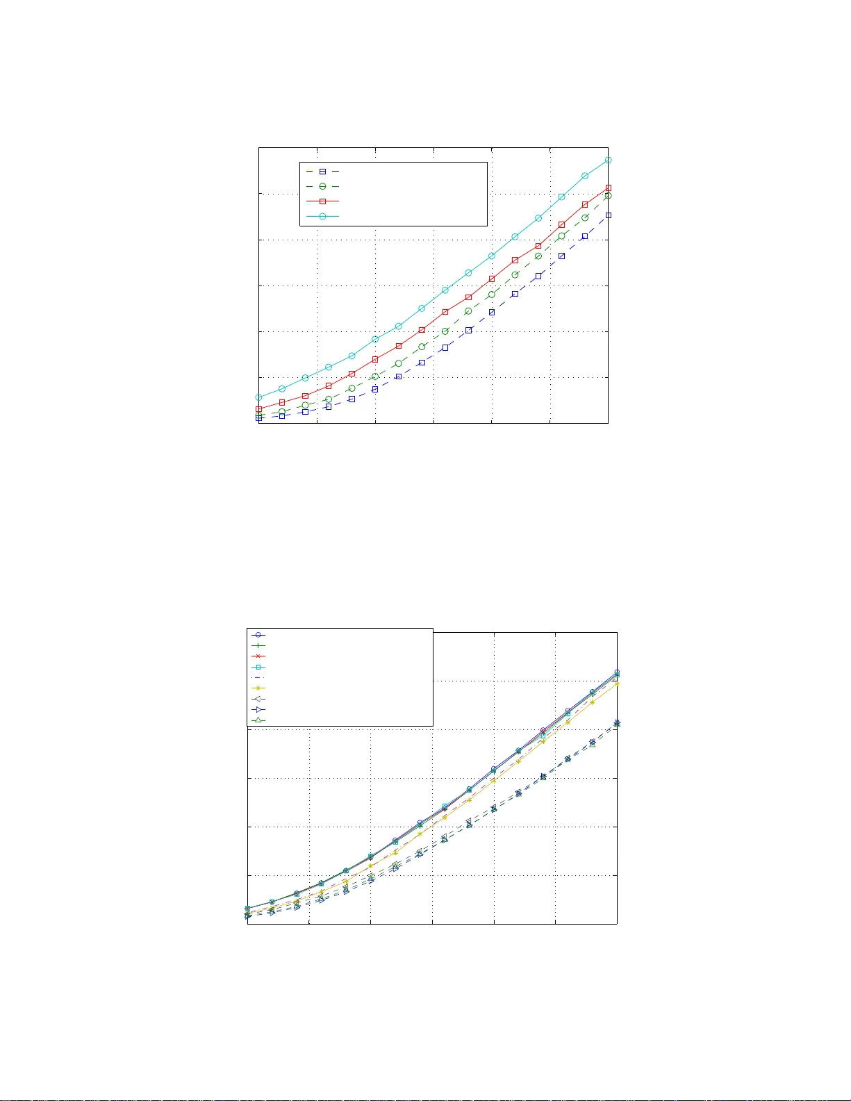
1 Optimal Relay-Subset Select ion and T ime-Alloca tion in Decode-a nd-F orwar d Cooperati ve Ne tw orks Elzbieta Beres and Ra viraj Adv e Dept. of Elec. and Comp. En g. Uni v ersity of T oronto 10 King’ s College Road T oronto, ON M5S 3G4, Ca nada email: ela.beres@utoronto.ca, r sadv e@comm.utoronto.ca Abstract W e present the optimal re lay-subset selection and transmission-time f or a deco de-and- forward, half-du plex cooper ati ve network of ar bitrary size. T he resource allocation is o btained by maximizing over the r ates obtained for each possible subset of acti ve relays, a nd the un ique time allocation for each set can be ob tained b y solvin g a linear system o f equations. W e also p resent a simple recu rsi ve algorithm for the optimiza tion problem which reduces the computatio nal load of finding the req uired matrix in verses, and reduce s the n umber o f req uired iterations. Our results, in terms of outag e rate, co nfirm the b enefit of adding po tential relays to a sma ll n etwork and the diminishing marginal retur ns for a larger network . W e also sh ow that o ptimizing over th e c hannel resou rces ensu res that more relays are acti ve over a larger SNR r ange, an d tha t lin ear n etwork constellation s significantly outperf orm grid constellations. Thro ugh simula tions, the optimization is sh own to be ro bust to no de nu mbering . I . I N T R O D U C T I O N Cooperation has become a popul ar techni que t o i mplement diversity in the abs ence of multip le antennas at receiving and transmi tting nodes [1]–[3]. In this context, resource allocation in cooperativ e networks has recently become an acti ve research area, and has been in vestigated under many s cenarios and metrics. In this paper , we address the problem of resource allocation, in terms of channel resources (t ime or bandwidth), in mu lti-relay networks w ith arbitrary connections . W e describe the contributions of the paper in detail after a brief revie w of the pertinent literature. For the single-relay case, se veral works ha ve dealt with v arious aspects of resource a llocation, in terms of power and/or bandwidth and time. Y ao et al. determine the optimal po wer and time allocation for relayed transmissio ns sp ecifically in the low-powe r regime [4]. L arsson and Cao present v arious strategies for allocating power and channel resources under ener gy constraints [5]. For the channel resource allocation problem, ho we ver , the aut hors consider selecti on combi ning o nly and do not address t he scenario of joint decoding o f the source and relay signals. T he works i n [6]–[8] address the problem of po wer and channel resource allocatio n under sum average power constraint s. Optimal tim e and bandwidt h allocation usin g 2 instantaneous and aver age channel cond itions is obtained us ing po wer control in [9]. Channel resource allocation under fix ed p o wer is developed in [10] In networks with mult iple relays, the a vailable literature can be classi fied into two groups: n etworks where relays do not communicate with one another (parallel-relay networks), and networks without restrictions on relay comm unication (arbit rarily-connected networks). Resource allocation for the for- mer has been addressed in [11]–[14]. Ibrahimi and Liang dev elop the optim al power allocation for a multi -relay cooperative OFDMA ampli fy-and-forward (AF) syst em [11]. By maximizing the channel mutual informati on, Anghel et al. find the optimal p o wer allocation for mult iple parallel relays in AF networks [12], [13]. A more general sol ution is given in [14] where the auth ors give the opti mal powe r and channel resource allocation for a p arallel-relay network wit h individual power constraints on the nodes. T o the best of our kn owledge, the problem of channel resource allocati on for arbitrarily-connected networks and dedicated multi ple access has not been addressed in the literature. In general, works in the area of multi-relay systems wi th arbitrary links generally neglect t he bandwidth penalty arising from multiple hops by assuming either full-dupl ex no des, a bandwid th-unconstrained system, or the ava ilability of channel phase informatio n at the transmitter [15]–[27]. These assumpt ions, howe ver , are not realistic for practical wireless networks, where nodes are likely to be h alf-duplex, phase information is very difficult t o obtain at t he transmit ter , and bandwi dth is a scarce resou rce. T o fill t his v oid, in this paper we in vestigate the problem of resource allocation i n a bandwidth-constrained, cooperative, decode-and-forwar d (DF), wireless network, and consid er the m ost general setting where multiple relays can transmit can cooperate with each other in transmitting information between so urce and destinati on. In this setting, we address the joint problem of opt imal selection of a relaying subset and allocation of tim e resources to the selected relays. The resource allocation is framed in the context of mesh networks of relati vely simple and inexpensive nodes. W e concentrate on resource allocation in terms of transmission tim e only , removing po wer all ocation from t he o ptimization; we furth er simply the problem by consi dering orthogo nal transmis sions. This is mo tiv ated by the need to reduce complexity , allowing for nodes which can implement the resource all ocation simpl y by s witching on and of f. For a s ystem w ithout power all ocation, a sol ution to this problem provides an upper b ound on cooperativ e performance in multi-relay network where dedicated channels are ass igned for each source transmissio n. 3 T o t he best of our knowledge, no other work provides a solu tion t o time-allocation for an arbitrarily connected cooperative network. The solutio n can be interpreted as a generalizatio n of the opport unistic protocol presented by Gunduz and Erki p, wh ere t he relay is activ e o nly when it increases the outage rate [6]. In terms of th e resource allocation solutio n, it is also a generalization of the solution in [10], where channel resource allocation is determined und er fixed powe r for a three-node DF network. Th e soluti on can also b e int erpreted as a generalizatio n of no de selection [3], [28]–[30] under relaxed transmi ssion constraints, where transmiss ion can occur on mult iple time-slots and relays can communicate with one another . This paper is st ructured as follows. Section II describes the sys tem model. In Section III and IV we develop the proposed resource allocation schem e and present a si gnificantly simpli fied recursiv e implementati on. Simulation results are presented in Section V and concluding remarks are p resented in Section VI. I I . S Y S T E M M O D E L W e consider a mesh network of static nodes comprisin g a source and d estination node and N pot ential relays. The inter-node channel powers are denoted as | a ij | 2 , where i and j represent th e source node s , relay nodes r k , k = 1 . . . N , or the dest ination n ode d . They are assumed ind ependent of each other and are m odelled as flat, slowly-fading and exponential wi th parameter λ . λ is in ve rsely prop ortional to the a verage channel p owe r and is a function o f inter-node distance, d ij , through the path l oss exponent p a , e.g., 1 /λ sd = (1 /d p a sd ) , and 1 /λ r k d = (1 /d p a r k d ) . W e do not include s hadowing into the fading model, altho ugh this can easily be in corporated on an instantaneous basis. Because th e nodes are static, the channels are assumed to change very slowly with ti me; we t hus assume kno wledge of all channel gain s (although not channel phases) at a centralizing unit. Th is kno wledge is essential to our resource allocation scheme. W ith the aim o f design ing simple and cheap nodes, we assume half-duplex channels and orthogonal transmissio ns, which greatly simplifies recei ver design. The relays are assumed to be numbered in some con v enient order s uch that relay r j transmits after r i if j > i . For example, the relays may b e in a linear con stellation as shown in Figure 1. W e also assum e the DF cooperatio n strategy wi th independent codebooks, which al low for the optimi zation of system resources (see [31 ] for an overvie w on current coding methods for nodes using DF). Note that repetition coding does not allow for this resource a llocation. W ith these assum ptions, the cooperatio n framew ork for the N -relay fully -connected network is as follows. The half-duplex constraint precludes the relays from transmi tting and recei ving simultaneousl y 4 on the same channel, and the unav ailability of forward-channel phase information at th e nodes precludes the nodes from si multaneous transmissions. The transm ission between the source and destination is thus divided into N + 1 time-slots, of duration t 0 , t 1 , . . . , t N , with t 0 + t 1 + . . . + t N = 1 . In t he first t ime-slot, the s ource transm its its information to all the nodes. T he first relay , r 1 , decodes this information and t he remaining N relays and the destination store the inform ation for future processing. In the second slot, of duration t 1 , the first relay re-transmits the information using an in dependent cod ebook, the second relay decodes the inform ation from the first relay and the source, and the remaining N − 1 relays and the destination store the information for further processin g. In general, each relay r k decodes information from the source and from the pre vious relays r 1 . . . r k − 1 up to and i ncluding time-sl ot t k − 1 . Th is process continues until all relays hav e t ransmitted and the destinati on attempt s to decode the i nformation. Assuming that each node uses power P and W Hz per transmiss ion (noting that altho ugh each node transmits for a different amount of tim e, the symbo l d urations and thu s t he corresponding bandwi dth used by each node is the sam e), the signal to noise ratio (SNR) at node j result ing from t ransmission from node i can be written as SNR ij = P N 0 W | a ij | 2 , where N 0 is the noise spectral density . In the rest of the paper , we us e the short-hand notati on L ij to deno te log 2 (1 + SNR ij ) , the capacity of th e corresponding channel. I I I . O P T I M A L R E S O U R C E A L L O C A T I O N A N D R E L A Y S E L E C T I O N In this s ection, we solve th e j oint p roblem of resource allocation and relay selection for the network discussed above. Essentially , we g iv e the optimum values of t i , i = 0 . . . N , s uch that the achie v able rate between source and destination is maximized. W e begin here with a fully-connected netw ork, wh ere each node is l inked to all other n odes through a non-zero channel. A. Fully Connected Network Consider a source-destinati on pair communicating wi th the help of N relays. As suming th at each relay is acti ve, the mutual i nformation at each relay and destination can be written as I 1 ( t 0 ) = t 0 L sr 1 , (1) I k ( t 0 , t 1 , t 2 , . . . , t k − 1 ) = t 0 L sr k + t 1 L r 1 r k + . . . + t k − 1 L r k − 1 r k , (2) I D ( t 0 , t 1 , t 2 , . . . , t k , . . . , t N − 1 , t N ) = t 0 L sd + t 1 L r 1 d + . . . + t k − 1 L r k − 1 d + . . . + t N L r N d , (3) 5 where I k and I D denote the mutual inform ation at relay r k and t he destination, respectively . W ith al l N relays cooperating, the maxim um achie v able rate under orthogonal transmissio ns is the minimum of th e mutual in formation obt ained at each individual relay node: R N = max t 0 ,...,t N min { I 1 ( t 0 ) , I 2 ( t 0 , t 1 ) , . . . , I k − 1 ( t 0 , . . . , t k − 2 ) , I k ( t 0 , . . . , t k − 1 ) , I k +1 ( t 0 , . . . , t k ) , . . . , I N ( t 0 , . . . , t k , . . . , t N − 1 ) , I D ( t 0 , . . . , t k , . . . , t N − 1 , t N ) } , (4) suc h that t i ≥ 0 , ∀ i, t 0 + t 1 + . . . t N ≤ 1 . The above expression is a straightforward generalization of t he cut-set bound for the single-relay network. This generalization maintains o rthogonal transmissions for each relay , a model which represents practical networks with si mple nodes that cannot implement comp lex interference cancelation. W e use th is mo del as the basis of the optimization in the rest of this paper . W e note, howe ver , that because each relay t ransmits using an orthogonal channel, R N is clearly not the channel capacity . For l iterature on the channel capacity of arbitraril y-connected networks, we direct the reader to [32]–[37] for full-duplex relays, and [38] for half-duplex relays. For reasons that will soon becom e clear , let us con sider the case with relay r k removed from the network. The maximu m achiev able rate R k N − 1 becomes R k N − 1 = max t 0 ,...,t k − 1 ,t k +1 ,...t N min { I 1 ( t 0 ) . . . , I k − 1 ( t 0 , . . . , t k − 2 ) , I k +1 ( t 0 , . . . , t k − 1 ) , (5) . . . , I D ( t 0 , . . . , t k − 1 , t k +1 , . . . , t N ) } , suc h that t i ≥ 0 , ∀ i, t 0 + . . . t k − 1 + t k +1 + . . . t N ≤ 1 . Removing relay r k is th us equiv alent to removing t k and I k from the opt imization. [W e u se the subscrip t in R k N − 1 to denote the m aximum number of potenti ally active relays, and the superscript to denot e th e relay removed]. The maximum rate at which the source can transmit to the destinatio n can th us be written as the maxim um of the rate obt ained by using all N relays, and the rate obtained by successiv ely removing each relay: R T = max { R N , R 1 N − 1 , R 2 N − 1 , . . . , R N N − 1 } . (6) 6 If R T = R k N − 1 , the maxim um rate can be ob tained by i terating through (4) and (5), successively removing a relay each st ep. Note that obt aining R k N − 1 includes the cases where t wo or more relays are removed. In theory , therefore, all 2 N possible cases must b e checked. Let ( t ∗ 0 , t ∗ 1 , . . . , t ∗ N ) deno te the resource all ocation that solves the optimization problem . W e begin an outline of the solut ion to the optimization problem i n (4), (5) and (6) with th e following propo sition. Pr oposition 1: W ith a maximum num ber of potential relays N , t he m aximum achiev able rate R T = R N only if t ∗ k 6 = 0 , ∀ k . Otherwise, if t ∗ k = 0 , R T = R k N − 1 . Pr oof: W ith exactly N activ e relays, and with k < n < N , the resulting rate can be written explicitly as: R N = max t 0 ,...,t N min { ( t 0 L sr 1 ) , ( t 0 L sr 2 + t 1 L r 1 r 2 ) , . . . , ( t 0 L sr k + . . . + t k − 1 L r k − 1 r k ) , ( t 0 L sr n + . . . + t k − 1 L r k − 1 r n + t k L r k r n + t k +1 L r k +1 r n . . . t n − 1 L r n − 1 r n ) , . . . , ( t 0 L sd + . . . + t k − 1 L r k − 1 r d + t k L r k r d + t k +1 L r k +1 r d + . . . t N L r N r d ) } . (7) Setting t k = 0 gi ves R N = max t 0 ,...,t k − 1 ,t k +1 ,...t N min { ( t 0 L sr 1 ) , ( t 0 L sr 2 + t 1 L r 1 r 2 ) , . . . , ( t 0 L sr k + . . . + t k − 1 L r k − 1 r k ) , ( t 0 L sr n + . . . + t k − 1 L r k − 1 r n + t k +1 L r k +1 r n . . . t n − 1 L r n − 1 r n ) , . . . , ( t 0 L sd + . . . + t k − 1 L r k − 1 r d + t k +1 L r k +1 r d + . . . t N L r N r d ) } (8) ≤ max t 0 ,...,t k − 1 ,t k +1 ,...t N min { ( t 0 L sr 1 ) , ( t 0 L sr 2 + t 1 L r 1 r 2 ) , . . . , ( t 0 L sr n + . . . + t k − 1 L r k − 1 r n + t k +1 L r k +1 r n . . . t n − 1 L r n − 1 r n ) , . . . , ( t 0 L sd + . . . + t k − 1 L r k − 1 r d + t k +1 L r k +1 r d + . . . t N L r N r d ) } (9) = R k − 1 N − 1 , (10) since (9) has one fe wer term in the mini mization than (8). T o solve the optim ization problem of (4) we thus require only the critical poin ts for whi ch t ∗ k 6 = 0 , ∀ k . In the following propositio n, we show t hat for each R N , i.e., giv en a set of po tential relays, only one solution satisfies t ∗ k 6 = 0 , ∀ k . Pr oposition 2: The uniq ue solution to the optim ization problem in the minim ization in (4) for which t ∗ k 6 = 0 , ∀ k is giv en by I 1 ( t 1 ) = I 2 ( t 1 , t 2 ) = . . . = I N ( t 1 , . . . , t N ) = I D ( t 1 , . . . , t N ) . Pr oof: W e consider all possible crit ical poi nts obtained from the optimizatio n in (4). The point s are 7 obtained either by maximizing each individual term in (4) or b y intersecting all possible combinations of the terms in (4). W e show that th e on ly sol ution leading to no n-zero so lutions result s from int ersecting e very term in (4). The criti cal points for the optimizatio n problem can be ob tained b y so lving th e follo wing: 1) Maxi mize t he individual terms in (4) except I d ( t 0 , . . . , t N ) : ∀ k ≤ N , max t 0 ,...,t k − 1 I k ( t 0 , . . . t k − 1 ) s . t . t 0 + . . . + t k − 1 ≤ 1 . (11) Because the optimizatio n is not ov er t m , ∀ k ≤ m ≤ N , the soluti on to this problem clearly has all t m = 0 , ∀ k ≤ m ≤ N , and thus cannot be a solution to the overall optimization problem. 2) Maxi mize I d ( t 0 , . . . , t N ) : max t 0 ,...,t N I d ( t 0 , . . . t N ) = max t 0 ,...,t N { t 0 L sd + . . . + t N L r N r d } , s . t . t 0 + . . . + t N ≤ 1 . (12) In t his case, all variables are included in th e opt imization. It is easy t o s how , ho wev er , that this func- tion is maxim ized b y selecting the largest L v alue, i.e., ev aluating t he Kuhn-T ucker condi tions l eads to a solution of the f orm t m = 1 , t k = 0 , ∀ k 6 = m , where m = arg max k { L sd , L r 1 d , . . . , L r k d , . . . , L r N d } . Therefore, this solution i s also not a solution to the overall optimization problem. 3) Maxi mize the functio n that result s from the in tersection of all possible com binations of the functi ons I k . Let M denote all possible subsets of { 1 . . . N } . M then contains 2 N such subsets, i.e., |M| = 2 N . Consider one such subs et δ k = ( m 1 , m 2 , . . . , m k ) , with m 1 < m 2 < m k . On e critical p oint then is max t 0 ,...,t m k − 1 I m k ( t 0 , . . . t m k − 1 ) (13) such that I m 1 ( t 0 , . . . t m 1 − 1 ) = I m 2 ( t 0 , . . . t m 2 − 1 ) = . . . = I m k ( t 0 , . . . t m k − 1 ) . (14) This optimization then gets r epeated for all sets δ k ∈ M . In all but one combination, this optimization is not over all the v ariables { t 0 , . . . t N } . As in point (1), this maximization also leads to t k = 0 for some value of k . 4) Maxi mize t he intersection o f all terms in (4): I 1 ( t 0 ) = I 2 ( t 0 , t 1 ) = . . . = I N ( t 0 , . . . , t N − 1 ) = I d ( t 0 , . . . , t N ) . (15) 8 This is the only case that leads to t k 6 = 0 , ∀ k = 0 . . . N . Essentially , this proposition shows that if all N relays are to contribute, all terms in t he minim ization in (4) m ust be equal. This propositi on applies to any value of N . Therefore, if t he optimal solut ion has k < N relays, an expression like (4) can be written for tho se k relays. B. Optimal solution The linear syst em of equation s in (15) has a simple solu tion. Setting each equation to a cons tant, sol ving for the ve ctor o f unkno wns t = ( t 0 . . . t N ) and normalizing, we obtain L N + 1 t N +1 = 1 N +1 , ⇒ t N +1 = L − 1 N +1 1 N +1 || L − 1 N +1 1 N +1 || 1 = L − 1 N +1 1 N +1 1 T N +1 L − 1 N +1 1 N +1 , (16) where || v || 1 denotes the sum of t he elements of v , i .e., the 1 -norm. 1 N +1 is the lengt h- ( N + 1 ) vector o f ones and L N +1 is the ( N + 1) × ( N + 1) rate matrix L N +1 = L sr 1 0 0 . . . 0 L sr 2 L r 1 r 2 0 . . . 0 L sr 3 L r 1 r 3 L r 2 r 3 . . . 0 . . . . . . . . . . . . 0 L sd L r 1 d L r 2 d . . . L r N d . (17) The sol ution in (16 ) d oes not guarantee that the const raint t k > 0 ∀ k = 0 . . . N is satisfied. T o ensure that onl y soluti ons for w hich this cons traint is satisfied are considered, we again consider the set M . Each entry in th e set corresponds to a rate matrix, L m , simi lar to t hat in (17), formed us ing t he relays in that entry of t he set. Furthermore, let | m | denot e t he size of the rate matrix L m . A relay set and i ts corresponding so lution, denoted as t m , is includ ed as a potential solution if t m satisfies the constraint, i.e., t m > 0 | m | , (18) where 0 | m | is the all -zero v ector of size | m | , 0 | m | = [0 , 0 , 0 , . . . 0 ] T and the inequ ality operates on an element-by-element basis. Let the set K form the subset of M that comprises all potential s olutions. Let L k , t k and | k | denote the rate matrix, it s correspond ing solution and size, respectiv ely , fo r each ent ry of the s et K . No te that the n umber of acti ve relays bein g consi dered in each entry is | k | - 1. Finally , th e 9 optimum so lution can be obtained by solving (16) for all possible combin ations of acti ve relays in the set K i.e., t ∗ = max K L − 1 k 1 | k | 1 T | k | L − 1 k 1 | k | , ∀ k = 1 , . . . , |K | . (19) Giv en that entry k ∗ corresponds to t ∗ , the maximum achiev able rate vector can thus be written as L k ∗ t ∗ = L k ∗ L − 1 k ∗ 1 | k ∗ | 1 T | k ∗ | L − 1 k ∗ 1 | k ∗ | = 1 | k ∗ | 1 T | k ∗ | L − 1 k ∗ 1 | k ∗ | , (20) and the maxi mum achiev able rate, R ∗ , is R ∗ = 1 1 T | k ∗ | L − 1 k ∗ 1 | k ∗ | , (21) Note that the solution described above is equ iv alent to the iterativ e maxim ization i n (6), and that removing a relay r k translates to removing t he k th row and ( k + 1) th column from the rate m atrix i n (1 7). Removing the first relay , for example, reduces the rate matrix in (17) to L N = L sr 2 0 . . . 0 L sr 3 L r 2 r 3 . . . 0 . . . . . . . . . 0 L sd L r 2 d . . . L r N d . (22) Since |M| = 2 N , 2 N possible solutions m ust be test ed to find the global o ptimum. C. Numbering In Section III-A, we ga ve the solution t o the opt imization probl em for a network wit h nodes num bered as i n Fig ure 1. T he num bering of the relay nodes impacts performance through causali ty: relay r k decodes information from relay r k − 1 , but no t vice-versa. A complete solu tion to the optimi zation prob lem must therefore t ake into account an optimal numbering s cheme. In the worst case (in terms of compu tational power) , an optimal solution can be obtained for a specific numbering scheme, and the truly optimal solution can be maxim ized over all possible numbering s chemes. Clearly , such an approach is im practical. Althoug h a search for an optimal or ef fecti ve sub-optimal solution is beyond t he scope o f this paper , we st udy the ef fects of numbering on the soluti on and result ing rate by consid ering some numbering schemes based o n heuristics. W e consider two approaches: num bering 10 based on average channel conditions, and numbering based on instantaneous channel condit ions. 1) Numberi ng based on avera ge channel conditi ons: In the case of the linear network in Figure 1, the numb ering is trivial: node numbers increase away from t he source and to wards the destination. In the case of square net work with nodes arranged in a grid, we consider t wo numberings which we refer to as A verage Descending Numbering and A verage Linear N umbering , shown in Figures 3 and 2, respectiv ely , for a 4 × 4 network. • A verage Descending numbering : node numbers increase to wards the destinatio n and downw ards, • A verage Linear number ing : node numbers i ncrease towards th e destination but vertical numbering ensures t hat nodes clo sest t o each ot her retain close numbering. 2) Numberi ng based o n in stantaneous c hannel conditions: • Instantaneous S − R k numbering : no de numbers increase with increasing source-relay channels. The first node has t he best source-relay channel, the second node has the second-best source-relay channel, et c. • Instantaneous R k − R m numbering : nodes are numbered to maxi mize the channel between adjacent nodes. The first relay has the best source-relay channel. The second relay has the strongest r 1 -relay channel. Num bers are assign ed in this process to unoccupied relays. T his heuris tic is based on the notion that w e should maxim ize the capacity of each ( R k , R k +1 ) hop. • Random numbering : nodes are numbered randomly . This case e valuates the worst-case scenario and t ests the robustness of the optim ization to numbering. These schemes are ev aluated via simulat ions in Section V. As we will see, the achiev able rate is remarkably robust to the chosen num bering s cheme. D. P artially Connected Network In this section we briefly discuss the more practical case of a parti ally connected network in whi ch some links between the no des in th e network are una vailable. This is a generalization of the fu lly-connected network di scussed in Section III-A above. Such a network is more li kely to represent a large scale network where, in an y case, the soluti on in (19) would be computation ally infeasible. As an example, consider the two-relay network with the link bet ween r 1 and r 2 is removed. The rate 11 matrix thus b ecomes L 3 = L sr 1 0 0 L sr 2 0 0 L sd L r 1 d L r 2 d . (23) Removing the link thus reduces the rank of this matrix by o ne, and the rate matrix is now non-in v ertible, eliminating the so lution defined by I 1 = I 2 = I 3 , where both relays are active. The optimal solution in this case is t hus to select r 1 , r 2 , or no t to relay . Note, howe ver , that removing a link does no t automatically lead to a non-in ver tible rate m atrix. Consider , for example, the three-relay network with the link between r 1 and r 3 removed. The corresponding rate matrix L 4 = L sr 1 0 0 0 L sr 2 L r 1 r 2 0 0 L sr 3 0 L r 2 r 3 0 L sd L r 1 d L r 2 d L r 3 d (24) is full-rank and inv ertib le. The approac h to the optimizatio n problem for the case of the arbitrary connected network is that the same as for t he fully-connected network, wit h the exception that the rate matrix L N +1 may no t be in vertible, in which case the corresponding solution is in admissable. Th e remaining steps remain unchanged. I V . I M P L E M E N T A T I O N W I T H R E D U C E D C O M P L E X I T Y The solution to the opti mization prob lem in (4), (5) and (6) inv olves checking 2 N potential solutions. Although t he process is conceptually simple, each solutio n in volves the in verse of a rate matrix. In this section, we show how t he optimization problem in the previous secti on can be significantly simpl ified using a recursiv e solutio n. This solution, which exploits the special structure of the rate matrix, greatly simplifies the matrix in version, as well as reduces the number of possible solutions to check. E ssentially , while t he s olution in Section III-A was a top-down approach, the approach we suggest here is b ottom-up. Consider a set of p relays, P = { r 1 , r 2 , . . . , r p } , p ≥ 0 , and its correspond ing rate matrix L P p +1 , sol ution vector t P p +1 and maximum rate (if ava ilable) R P . W e not e that if p = 0 and the set is empty , the rate matrix and solution ve ctor are constants, L sd and 1 , respecti vely . Denote as P ′ the set P append ed with another relay , i.e., P ′ = { r 1 , r 2 , . . . , r p , r p +1 } . Denote as L P ′ p +2 , t P ′ p +2 , and R P ′ the matrix, solut ion vector 12 and rate correspon ding to set P ′ . Pr oposition 3 : Given L P p +1 − 1 , L P ′ p +2 − 1 can be obtained with computational complexity order of O ( p 2 ) Pr oof: For p ≥ 0 , the rate matrix L P ′ p +2 can be writ ten as L P ′ p +2 = L P p +1 (1 : p, 1 : p ) 0 p × 2 F 2 × p T 2 , (25) where L P p +1 (1 : p, 1 : p ) denot es the first p rows and columns of the rate matrix L P p +1 , 0 p × 2 is a ( p × 2) matrix of zeros, T 2 is a (2 × 2) l owe r- triangul ar matrix, and F 2 × p is a (2 × p ) full y-loaded matrix. Note that L P p +1 (1 : p, 1 : p ) i s t riangular . Usin g t he inv erse o f a partitioned matrix [39], L P ′ p +2 − 1 can be writt en as L P ′ p +2 − 1 = L P p +1 (1 : p, 1 : p ) − 1 0 p × 2 − T − 1 2 F 2 × p L P p +1 (1 : p, 1 : p ) − 1 T − 1 2 . (26) Note that L P p +1 (1 : p, 1 : p ) − 1 is th e in verse of a parti tion of th e triangular matrix L P p +1 . Using the in verse of a p artitioned matrix one more time, ho we ver , it is easy to see that L P p +1 (1 : p, 1 : p ) − 1 = ( L P p +1 ) − 1 (1 : p, 1 : p ) , (27) and thus L P ′ p +2 − 1 = ( L P p +1 ) − 1 (1 : p, 1 : p ) 0 p × 2 − T − 1 2 F 2 × p ( L P p +1 ) − 1 (1 : p, 1 : p ) T − 1 2 , (28) and hence o btaining L P ′ p +2 − 1 is an O ( p 2 ) operation. Using thi s above propos ition, the solution vector t P ′ p +2 of L P ′ p +2 can be obtained from the soluti on vector t P p +1 of L P p +1 : t P ′ p +2 = L P ′ p +2 − 1 1 p +2 1 T p +2 L P ′ p +2 − 1 1 p +2 = t P p +1 (1 : p ) t P ′ p +2 ( p + 1) t P ′ p +2 ( p + 2) , (29) where t P p +1 (1 : p ) represent the first p entries of the already-calculated so lution vector t P p +1 , and t P ′ p +2 ( p + 1) 13 and t P ′ p +2 ( p + 2) are the last two entries of t he solut ion vector t P ′ p +2 that remain to be calculated. R P ′ = 1 1 T p +2 ( L P ′ p +2 ) − 1 1 p +2 is the maxi mum achie vable rate obt ained using the set P ′ of relays. Th e last two entries of the sol ution vector t P ′ p +2 ( p + 1) and t P ′ p +2 ( p + 2) can be written as t P ′ p +2 ( p + 1) t P ′ p +2 ( p + 2) = R P ′ h − T − 1 2 F 2 × p L P p +1 − 1 (1 : p, 1 : p ) T − 1 2 i 1 ( p +2) × 1 , (30) W ith a corresponding achiev able rate R P ′ R P ′ = 1 1 T p +2 L P ′ p +2 − 1 1 p +2 = X ij L P ′ p +2 − 1 ( i, j ) ! − 1 , = X i,j L P p +1 − 1 ( i, j ) − X i,j T − 1 2 F 2 × p L P p +1 − 1 (1 : p, 1 : p )( i, j ) + X ij T − 1 2 ( i, j ) ! − 1 , (31) where we use P i,j A ( i, j ) t o denote the summ ation over all the elements of matrix A . Using the abov e, the opt imization probl em for a n etwork of N potential relays can be sol ved recursi vely as follows: 1) Determin e the set of all potential relay combin ations. Sequence the set as: M = { ( r 1 ) , ( r 1 , r 2 ) , ( r 1 , r 2 , r 3 ) , . . . ( r 1 , r 2 , . . . , r N ) , ( r 1 , r 3 ) , ( r 1 , r 3 , r 4 ) , . . . , ( r 1 , r 3 , . . . , r N ) , . . . . . . ( r 1 , r N ) , ( r 2 ) , ( r 2 , r 3 ) , ( r 2 , r 3 , r 4 ) , . . . ( r 2 , r 3 , . . . , r N ) , ( r 2 , r 4 ) , ( r 2 , r 4 , r 5 ) , . . . , ( r 2 , r 4 , . . . , r N ) , . . . . . . ( r 2 , r N ) , . . . ( r N − 1 , r N ) } . 14 Note that each “ro w” of M is a subset of relay comb inations in which each elem ent is formed from the pre v ious element by adding a relay . 2) In each “ro w”, obtain t he rate matrix, i ts respective opt imized t ime allocation vector and achie vable rate for each element (i.e., relay combination) recursively using (28), (29), (30) and (31). 3) Check t hat for each particular set P of p relays, the solut ion t p and achie vable rate R p satisfies the constraints: R P ≥ 0 , (32) t P p +1 > 0 p +1 . (33) • If both constraints are satisfied, place the solution in the potential set of v ali d s olutions K , adva nce elements and return to step (1) . • If (33) is not satisfied, check which element of the the allo cation vector t p does not sati sfy the constraint. – If any of th e first ( p − 1) entries of t p are less than zero, i.e., t p (1 : p − 1 < 0 p − 1 ) , this constraint will not be satisfied for any other relay combinations in th is “row”. Advance rows and return to item (1) . – If the constraint is not satisfied by either o f the last two items in the solution vec tor , discard the s olution b ut check the other elements in the “ro w”. 4) From the set K , pick the hi ghest achie vable rate and its corresponding ti me all ocation. The recursi ve algorithm given above simplifies the op timization problem in two ways: 1) It reduces the computati on load of d etermining successiv e matrix inv erses by writing each matrix in verse as a function of anot her , already known, matrix in verse, and two ot her matrices obtained through simple matrix m ultiplication . 2) It may eli minate infeasible s olutions by dis carding relay combinations which do not satisfy con- straints. For example, if the relay combinati on ( r 1 , r 2 , r 3 ) does not satisfy the constraints, the combination ( r 1 , r 2 , r 3 , r 4 ) may be automati cally discarded. A. Complexity and Number of Operations In the next paper we will compare relay selectio n schemes partly on computatio nal complexity . In thi s section we calculate t his complexity , which also quantifies the computational sa vi ngs of the recursive 15 scheme presented above in Section IV. The compl exity of th e recursiv e scheme is bounded b y com plexity of matrix multiplicati on. The num ber of operations (mult iplications and additions) required in the p roduct of two matrices of size ( m, n ) and ( n, p ) is 2 mpn − mp [40], and the number of operations required for t he product o f a matrix of size ( m, n ) with a square, size- n diago nal m atrix i s m n − 1 X k =0 k + n X k =1 k ! = mn 2 . (34) W e no w calculate the n umber of operations required for each rate m atrix of size ( q + 1) , correspond ing to the s et Q ′ of q relays. Th e calculation of the matrix fundamental to the recursi ve algorithm , L Q ′ q +1 − 1 = − T − 1 2 F 2 × ( q − 1) L Q q − 1 (1 : q − 1 , 1 : q − 1) . (35) requires a t otal of 2 q 2 + 2 q + 1 operations, broken d o wn as: 1) − T − 1 2 → 5 operations, 2) − T − 1 2 F 2 × ( q − 1) = A 2 × ( q − 1) → 6( q − 1 ) operations u sing 2 mpn − mp , 3) A 2 × ( q − 1) L Q q − 1 (1 : q − 1 , 1 : q − 1) → 2( q − 1) 2 operations, using (34). From (31), the num ber of operations required to calculate R Q ′ is q 2 + 2 q + 4 . Using (30), the n umber of operations required to update the solution vector is 1 + 2( q + 1) = 2 q + 3 . Summing the above, we obtain the total number of operations required in one iteration of the resource allocation algorithm: Op( q ) = (2 q 2 + 2 q + 1) + ( q 2 + 2 q + 4) + (2 q + 3) = 3 q 2 + 6 q + 8 . (36) Note that t he complexity order of calculating each rate and solution vector is O ( q 2 ) . W i thout the recursion, this complexity is of order O ( q 3 ) , resulting from the i n verse of the rate matrix. The recursion thus introduces s ignificant sa ving s i n terms of complexity . W e now calculate the worst-case tot al number of operations required by the resource allocation algo - rithm. In the worst case, the algorith m cycles throug h 2 N operations consisti ng of N q sets of q relays which require 3 q 2 + 6 q + 8 operations. The total worst case number of operations is therefore N X q =1 N q (3 q 2 + 6 q + 8) . (37) This calculation could be rendered more precise if it were p ossible to account for the savings obtained in 16 Section IV which eli minates som e infeasible so lutions a priori by discarding relay combin ations known to not satisfy the cons traints. The probability of t his occurring for particular channel realizations is unfortunately very difficult to compute, and we thus show only the worst-case result. V . S I M U L A T I O N S In this section, we p resent results o f the resou rce allocation scheme dis cussed in Section III for networks with 1 t o 6 relays arranged linearly , and 4 and 9 nodes arranged in a g rid. The figure of merit is the achie vable rate R a with an outage probability of 10 − 3 , i.e. Pr[ R ∗ < R a ] = 10 − 3 . A closed form expression for t he ou tage prob ability of optimized cooperation is very complicated and beyond the scope of th e paper . The outage probabi lity and rate are thus obtained nu merically . The relays are equispaced on a line between the source and destination , as in Figure 1, and we use an attenuation exponent of p a = 2 . 5 . Th is choice is mot iv ated by the application of static mesh-nodes inst alled on pos ts; transmis sions between such no des shoul d undergo little shadowing and a lower attenuation exponent. From 60000 fading realizations we obtain the cumu lativ e d ensity function of the instantaneous rate F R ( r ) . The outage rate is the rate for which the probability o f outage is 10 − 3 , i .e., F − 1 R (10 − 3 ) . Figure 4 and 5 plot the outage rate as a function of the av erage end-to-end SNR, P N 0 W , for optimized and non-optimized cooperation, respectiv ely . The rate for the optimized cooperation is obtained from (19 ). Non-optimized coo peration uses equal time allocation, i .e., the rate for a particular relay set is simp ly the minimum of the mutual i nformation at each node. Non-optimized cooperation , howe ver , d oes opti mally select relays by choosing th e best , in terms of rate, of the 2 N relay combinatio ns. Comparing Figure 4 and Figure 5 s hows that opt imizing resources increases rates significantly , as expected. The outage rate increases as a function of nodes av ailable to relay . W e also note the typical phenomenon of decreasing marginal returns: the gains of adding each additional relay decreases with increasing nu mber of relays. Figures 6 and 7 show the a verage number of relays t hat are active from the set of potential relays for optimized and non-optimi zed cooperation. For each network size, this nu mber is a decreasing function. In- terestingly , the number of active relays decreases m uch faster for non -optimized as compared to opt imized cooperation, suggesting th at opt imizing resources dist ributes the relaying burden more effecti vely . T o test the ef fect of geometry on the ou tage rate, we com pare the rates o btained by op timizing resources and the placing relays o n a line, as in Figure 4 t o those obtained by placing the relays on a regular square grid. W e number t he relays in the grid in ascending order downwards and t o wards the s ource; a deriv ation of th e opti mal numbering is beyond th e scope of t his paper . The results are demonstrated in Figure 8, 17 where we place 4 and 9 relays on a 2 × 2 and 3 × 3 square grid. As sho wn i n the figure, the rate for the linear constellation is signi ficantly higher than that obtained by the grid constellation, suggesting that the path-loss incurred by traver sing all th e nodes laterally results in non-negligible performance loss. W e ev aluate t he performance of the num bering schemes discussed in Section III-C in Figure 9. The four schemes, including two based on ave rage channel condition s and two based on instantaneous channel conditions, exhibit indistingu ishable performance in terms of rate. There is an expected drop in rate with random numberin g, though we n ote that this drop is no more than approximately 0 . 25 bits/ channel use. The algorithm is thus quite rob us t t o numbering schemes. Figure 9 also shows the outage rate for a network with randomly placed nodes. Here the node locations are chosen from a uniform distribution ove r an area equi valent to that of the sq uare g rid . The internode channels are obtained as before. This example eli minates possibl e depend encies of t he results obtained earlier on the chosen array geomet ry . The numbering here is based o n the instantaneous S − R k channels. In su ch a random network, as expected, the av ailable outage rate is lo wer than i n a square grid network; howe ver , at higher SNR le vels th is dif ference disappears. Again, the significant gains due to resource allocation are clear . In Figure 9 we also compare the effect of n umbering when used without resource allocation, and show only the case of instantaneous S − R k numbering and random numbering. The improvement from instantaneous ov er random num bering in t his case is less t han 0 . 1 bi ts/channel use. The robustness of the numbering scheme thus increases by eliminating t ime optimi zation. T o gain in sight i nto this phenomenon, in Figure 10 we plot the ave rage number of active users for the instant aneous and random num bering schemes with and wi thout resource allocation . W e first observe t hat the instantaneou s numbering scheme uses more relays than the random numb ering scheme when resource all ocation is used, and that this diffe rence i s constant over the SNR region of interest. W ithout resource all ocation, on the other hand, the number of relays used when using inst antaneous and random numbering decreases quickly and is constant for SNR v alu es higher than 10 dB. It is clear from this figure t hat the dif ference in rate performance between instantaneous and random numbering is an increasing function of the number of selected relays. Because so few relays are s elected without resource allocati on, the ef fect of the n umbering scheme is negligible. The influence of the numbering scheme increases wh en time allocation is introduced, increasing the number of relays used for both nu mbering s chemes and increasing the sensitivity to th e nu mbering scheme. This sensitivity i ncreases slowly , howe ver , and is negligible for the var ious numbering schemes 18 based on heuris tics. V I . C O N C L U S I O N S In this paper , we d etermined the optim al channel resource allocation, in terms of time allo cation, for the N -node coop erati ve diversity , mult ihop n etwork using DF and independent codebooks. For a p articular network, i.e., set of potential relays, the unique solution for a particular relay numbering scheme is obtai ned by taki ng the i n verse of th e triangular rate matrix , and the optim al solution is fou nd by maximi zing over the rate for each possible network, given its maximum size. Throug h sim ulations, howe ver , t he optimizatio n is sho wn to be robust to the num bering scheme. W e show that by exploiting the special structure of the rate m atrix, the optimi zation can be performed in a recursi ve fashion whi ch decreases the computati on l oad of the rate matrix in verse and the number of required it erations. Node selection is inherent t o the optimizati on strategy . Simulation results show significant gains i n achiev abl e rate du e to resource allocation, but dimi nishing marginal returns as a function of network size. Furthermore, we show a significant benefit to arranging the nodes in a linear , as opposed to a grid, constellation. R E F E R E N C E S [1] A. S endonaris, E. Erkip, and B. Aazhang, “User cooperation div ersity - part I, II, ” IEEE T rans. Commun. , vol. 51, pp. 1927 – 1948, Nov ember 2003. [2] J. N. L aneman and G. W . W ornell, “Distri buted space-time-coded protocols for exploiting cooperati ve di versity in wireless networks, ” IEEE T rans. Inf. Theory , vo l. 49, pp. 2415 – 2425, October 2003. [3] E. Beres and R. Adve, “Selection cooperation in multi-source cooperati ve netw orks, ” IE EE T rans. W ireless Communications , vol. 7, pp. 118 – 127, Januaryr 2008. [4] Y . Y ao, X. Cai, and G. B. Giannakis, “On energ y efficienc y and optimum resource allocation of relay transmissions in the lo w-po wer regime, ” IEEE T rans. W ir eless Commun. , vol. 4, pp. 2917– 2927, Nov ember 2005. [5] E. G. Larsson and Y . Cao, “Collaborati ve t ransmit div ersity with adapti ve radio resource and po wer allocation, ” IEEE Commun. L ett. , vol. 9, pp. 511–513, June 2005. [6] D. Gunduz and E. Erkip, “Opportunistic cooperation by dynamic resource all ocation, ” IEEE T rans. W ir eless Commun. , vol. 6, pp. 1446 – 1454, April 2007. [7] J. Y ang, D. Gunduz, D. Brown III, and E . Erkip, “Resource allocation for cooperati ve relaying, ” in Proc. of Confer ence on Information Sciences and Systems (CISS 2008) , March 2008. [8] A. Host-Madsen and J. Zhang, “Capacity bounds and po wer allocation for wireless relay channels, ” IEEE T rans. Inf. Theory , vol. 51, pp. 2020 – 2040, June 2005. [9] L. Xie and X. Zhang, “Opportunistic cooperation for quality of service prov isionings over wireless relay networks, ” in Pr oc. of IEE E Int. Conf. on Communications , June 2007. [10] Y . Ning, T . Hui, C. Shasha, and Z. Ping, “ An adapti ve frame resource allocation strategy for TDMA-based cooperati ve tr ansmission, ” IEEE Commun. Lett. , vol. 11, pp. 417 – 419, May 2007. 19 [11] M. Ibrahimi and B. Liang, “Efficient powe r allocation in cooperativ e OFDM system wi th channel v ariation, ” in IEEE Internation al Confer ence on Communications (ICC) , May 2008. [12] P . A. Anghel, M. Kaveh, and Z. Q. Luo, “Optimal relayed po wer allocation in interference-free non-regenerati ve cooperativ e systems, ” in Pro c. of IEEE W orkshop on Signal Pr ocessing Advances i n W ir eless Communications , July 2004. [13] ——, “ An efficient algorithm for optimum po wer allocation in a decode-and-forw ard cooperativ e system with orthogonal transmissions, ” in Pro c. of the IEEE International Confer ence on Acoustics, Speech and Signal Pr ocessing ICASSP , May 2006. [14] Y . Liang, V . V eerav alli, and H. V . P oor , “Resource allocation for wireless fading relay channels: Max-min solution, ” IEEE T rans. Inf. Theory , vol. 53, pp. 3432 – 3453, October 2007. [15] J. Boyer , D. Falconer , and H. Y anikomerog lu, “Multihop diversity in wi reless relaying channels, ” IEEE T rans. Commun. , vol. 52, pp. 1820 – 1830, October 2004. [16] A. K. Sadek, W . Su, and K. J. R. Liu, “Multinode cooperativ e commun ications i n wireless networks, ” IEEE Tr ans. Signal Pro cess. , vol. 55, no. 1, pp. 341–3 55, January 2007. [17] Z. Y ang and A. Host-Madsen, “Routing and po wer allocation in asynchrono us Gaussian multiple-relay channels, ” EURASIP Jou rnal on W ir eless Communications and Networking , 2006. [18] J. Zhang and T . M. L ok, “Performance comparison of con ventional and cooperati ve multihop transmission, ” in Pr oc. of the W ir eless Communications and Networking Confer ence (WCNC) , April 2008. [19] S.-H. Chen, U. Mitra, and B. Krishnamachari, “Coope rativ e communication and routing over fading chan nels in wireless sensor network, ” in Pr oc. of the IE EE International Confer ence on W ireless Netw orks,Communications, and Mobile Computing (W ir elessCom) , June 2005. [20] X. Fang, T . Hui, Z. Ping, and Y . Ning, “Cooperativ e routing strategies in Ad Hoc networks, ” in Proc. of the IE EE V ehicular T echnology Confer ence (VTC-Spring 2005) , June 2005. [21] A. Khandani, J. Abounadi, E. Modiano, and L. Zhang, “Cooperati ve routing in wireless networks, ” in Proc. of All erton Conferen ce on Communications, Contr ol and Computing , October 2006. [22] F . Li, A. Lippman, and K. W u, “Minimum energy cooperati ve path routing in wireless network s: An i nteger programming formulation, ” in Pro c. of the 63th IEEE V ehicular T echnology Confer ence (IEEE VT C ’2006) , May 2006. [23] Y . Y uan, Z . He, and M. C hen, “V irtual MIMO-based cross-layer design for wireless sensor networks, ” IEEE T ransactions on V ehicular T echno logy , vol. 55, pp. 856– 864, May 2006. [24] Y . Y uan, M. Chen, and T . Kwon, “ A novel cluster-based cooperativ e MIMO scheme for multi -hop wireless sensor networks, ” EU RASIP J ournal on W ireless Communications and Networking , vo l. 2006, pp. Article ID 72 493, 9 pages, 2006. [25] V . Sriniv asan, P . Nuggeh alli, C.-F . Chiasserini, and R. Rao, “ An analytical approach to the study of cooperation i n wireless Ad Hoc networks, ” IEEE T rans. W ireless C ommun. , vol. 4, no. 2, pp. 722 – 733, March 2005. [26] L. Ong and M. Motani, “Optimal routing f or deco de-and-forw ard based coo peration in wireless networks, ” in Pr oc. of t he IEEE Confer ence on Sensor , Mesh and Ad Hoc Communications and Networks (SECON) , June 2007. [27] A. Aksu and O. Erceti n, “Reliable multi-hop routing with cooperati ve transmissions in energy-constraine d networks, ” IEEE T rans. Commun. , vol. 7, no. 8, pp. 2861– 2865, August 2008. [28] Y . Zhao, R. S . Adve, and T . J. Lim, “Improving amplify-and-forward r elay networks: Optimal po wer all ocation versus selection, ” IEEE T rans. W i r eless Commun. , vol. 6, pp. 3114 – 3123, August 2007. [29] A. Bletsas, A. K histi, D. Reed, and A. Lippman, “ A simple cooperati ve div ersit y method based on network path selection, ” IEEE J . Sel. Ar eas Commun. , vol. 24, pp. 659–672, March 2006. 20 [30] A. Bletsas, H. S hin, and M. Z. Win, “Cooperati ve communications wi th outage-op timal opportunistic relaying, ” IEEE T rans. W i r eless Commun. , vol. 6, no. 9, pp. 3450– 3460, September 2007. [31] A. Chakrabarti, E. Erkip, A. S abharwa l, and B. Aazhang, “Code designs for coo perativ e communication, ” IEEE Signal Pr ocessing Maga zine , vol. 24, pp. 16 – 26, S eptember 2007. [32] G. Kramer , M. Gastpar , and P . Gupta, “Cooperativ e strategies and capacity theorems for relay networks, ” IE EE Tr ans. Inf. Theory , vol. 51, no. 9, pp. 3037– 3063, S eptember 2005. [33] L. L. Xie and P . R. Kumar , “ An achiev able rate for the multiple-level relay channel, ” IE EE T rans. Inf. Theory , vol. 51, no. 4, pp. 1348 – 1358, 2005. [34] P . Gupta and P . R. Kumar , “T ow ards an information theory of large networks: an achie va ble rate region, ” IEEE T rans. Inf. Theory , vol. 49, no. 8, pp. 1877– 1894, August 2003. [35] S. A vestimehr , S. N. Digga vi, and D. N. C. Tse, “ Approximate characterization of capacity in Gaussian relay networks, ” in W ir eless Communications and Mobile Computing Confer ence (IWCMC) , August 2008. [36] A. Reznik, S. R. Kulkarni, and S. V erdu, “Degraded Gaussian multirelay channel: capacity and optimal powe r allocation, ” IE EE T rans. Inf. T heory , vol. 50, no. 12, pp. 3037–3046, December 2004. [37] P . Razaghi and W . Y u, “Parity forwarding for multiple-relay networks, ” IEE E Tr ans. Inf. Theory , 2007, submitted. A vailable online at http://www .comm.utoronto.ca/ ∼ weiyu/publications.html. [38] P . R ost and G. Fettweis, “ Achiev able rates in Gaussian half-duplex multiple relay networks, ” in Proc eedings if IEEE Global Confer ence on Communications (Globecom) , December 2008. [39] R. A. Horn and C. R. Johnson, Matrix Analysis . Cambridge Uni versity Press, 1985. [40] I. Kaporin, “ A practical algorithm for faster matrix multiplication, ” Numerical Linear Algebra with A pplications , vol. 6, pp. 687 – 700, 1999. 21 Fig. 1. L ocation of the relays with respect to the source and destination. Fig. 2. Numbering in a square 4 × 4 network in linear order Fig. 3. Numbering in a square 4 × 4 network in descending order −10 −5 0 5 10 15 20 0 1 2 3 4 5 6 Outage rate with resource allocation for 1 to 6 relays arranged in a line SNR (dB) Rate Fig. 4. Outage rate vs. S NR using 1 , . . . 6 potential relays and with resource allocation. 22 −10 −5 0 5 10 15 20 0 0.5 1 1.5 2 2.5 3 3.5 4 4.5 Outage rate with no resource allocation for 1 to 6 relays arranged in a line SNR (dB) Rate Fig. 5. Outage rate vs. S NR using 1 , . . . 6 potential relays and without resource allocation. 23 −10 −5 0 5 10 15 20 0.5 1 1.5 2 2.5 3 3.5 4 4.5 Average number of active relays with resource allocation for 1 to 6 Relays arranged in a line SNR (dB) Average Number of Relays Used 1 Relay 2 Relays 3 Relays 4 Relays 5 Relays 6 Relays Fig. 6. A verage number of activ e relays with 1 , . . . 6 potential relays and wit h resource allocation. −10 −5 0 5 10 15 20 0 0.5 1 1.5 2 2.5 3 3.5 Average number of active relays with no resource allocation for 1 to 6 Relays arranged in a lin e SNR (dB) Average Number of Relays Used Fig. 7. A verage number of activ e relays with 1 , . . . 6 potential relays and wit hout resource allocation. 24 −10 −5 0 5 10 15 20 0 1 2 3 4 5 6 SNR (dB) Outage Rate Outage rate with resource allocation for 4 and 9 relays arranged in a grid and in a line 4 Relays, Grid Constellation 4 Relays, Linear Constellation 9 Relays, Grid Constellation 9 Relays, Linear Constellation Fig. 8. Outage rate vs. S NR using resource allocation and for 4 and 9 relays arranged in a grid and in a l ine. −10 −5 0 5 10 15 20 0 1 2 3 4 5 6 Outage rate with 9 nodes SNR (dB) Rate Square Network, Instantaneous S−R k Square Network, Instantaneous Rk−Rm Square Network, Average Linear Square Network Average Descending Random Network, Instantaneous S−R k Square Network Instantaneous Random Square Network, Instantaneous S−R k NRA Square Network Random NRA Random Network Instantaneous S−R k NRA Fig. 9. Outage rate vs. S NR using resource allocation and for va rious numbering schemes f or 9 potential nodes arranged in a grid 25 −10 −5 0 5 10 15 20 0 0.5 1 1.5 2 2.5 3 Average number of relays used with 9 nodes arranged in a square SNR (dB) Number of Relay Instantaneous S−R k Instantaneous Random Instantaneous S−R k NRA Instantaneous Random NRA Fig. 10. A ve rage number of activ e relays using resource al location and with v ari ous numbering schemes for 9 potential nodes arranged in a grid
Original Paper
Loading high-quality paper...
Comments & Academic Discussion
Loading comments...
Leave a Comment