Multipath Amplification of Chaotic Radio Pulses and UWB Communications
Effect of multipath amplification is found in ultrawideband wireless communication systems with chaotic carrier, whereas information is transmitted with chaotic radio pulses. This effect is observed in multipath environment (residence, office, indust…
Authors: Yuri V. Andreyev, Alex, er S. Dmitriev (Member
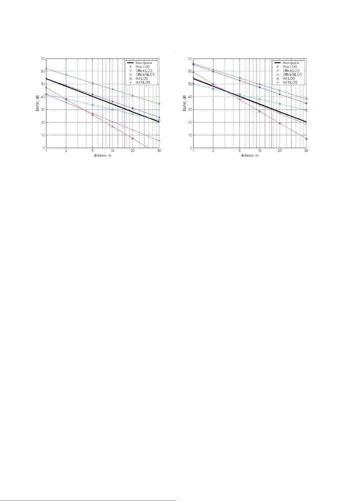
Abstract — Effect of multipath am plification is found in ultrawideb and wireless com munication systems with chaotic carrier, wh ereas inf ormation is transmitted w ith ch aotic radio pulses. This effect is observed in multipath environment (residence, of fice, industrial or other indoor space). It i s exhibited as an increase of s ignal power at the receiver inpu t with respec t t o the case of free spa ce. Multipath am plification effect gives 5–15 dB energy gain (depending on the environ ment) , w hich allows to have 2–6 times longer distance range for the same transmitt er power. Index Terms — Ultrawi deband communications, chaos, multipath channels, chaotic carrier, d igital communications I . I NTRODUCTI ON Recently , u ltrawideband (UWB) signals wer e introd uced i n practic e of publi c c ommunications. As a rule, UWB signals are defined as signals with relative bandwidth 2 ∆ f /( f u + f l ) > 0.25, where ∆ f = f u – f l , and f u and f l are u pper and lower boundaries o f the signal frequency band [1 , 2]. S ometimes, different definitions are used, e.g., sig nals with bandwidth ∆ f > 500 MHz [ 3]. UWB signals can be implemented wi th ultrashort pulses [ 1, 2, 4, 5], chaotic oscillations [6–9], OFDM modulation [10] , chirps [11]. Since 2002, so me countries permit ted unlicensed use of UWB communicati ons in 3– 10 GHz range, many others are in process [3, 12, 13]. In order to repe atedly use the already occupied frequency range and to avoid interfer ence wit h e xisting a nd f uture narrowband comm unications s ystems (e.g., Wi-Fi, W i-Max, etc.), permitted spectral density of UWB wireless communications in 3–10 GHz rang e is lim ited, e.g., in USA it is S ( f ) ≤ – 41.3 dBm/MHz. Thus, total emitted power in the entire permitted b and mu st no t ex ceed – 2.3 dBm (appr ox. 600 µW ). W ith o mni-directional antennae these restrictions confine the UWB signal application area to wireless communications at distances 1…10 (100) m. Majority of tasks to be solved by corresponding UWB commun ications sy stems occur in residence, office and i ndustrial, i.e. , in multi path i ndoor environment. Hence, the performanc e of UWB sy stems in m ultipath environment is of prime importance. Multipath p ropagation can severely impair the performance of a wireless digital communication sy stem. Ty p ical negative effects in narrowband communication sy stems are fading and inter-sy mbol i nterference [14]. To compensate for these effects, sophisticated constructions (e.g ., rake-receive r) were invented [14]. The behavior of a commu nication system in multipath environment is determined by its structure, the ty pe of carr ier signal and modulati on scheme. A few year s ago a concept of direct chaotic comm unications (DCC) was p roposed [ 6–9]. This concept is described in Secti on 2. IEEE S tandard Committee in cluded direct chaotic sy stems in IEEE 802.15.4a standard (as option). I n thi s p aper we theoretically consider operation of DCC systems in multipath channel an d show that for such systems there is a unique effect which we ca ll “ m ultipath amp lification”, and which at certain system parameters exh ibits it self as an Multipath Am plification of Ch aotic Radio Pu lses and UWB Comm un ication s Yuri V. Andreyev, Alexander S. Dmitriev, Member, IEEE , Andrey V. Kl etsov increase of a verage signal power at the output of the rece iver with respect to « free-space» case. I n S ection 3 the natu re of multipath amplification effect is discussed. To simulate operation of a communication system in multipath environment, m ultipath channel mod els are necessary . These models are presented in S ection 4, a nd estimates of multipath gain are obtained in S ection 5. I n Section 6 conditions for this effect are summarized . Effect of multipath amp lification on the range of co mmunication sy stem with chaotic radio pulses (for I EEE 802 .15.4a standard) is evalua ted in Section 7. I I. DC C TECHNOLOG Y The technology of di rect chaotic c ommunications is based on the use of chaotic signals, which are irregular oscillations produced by deterministic systems [ 15]. Ir regula r behavior of s uch systems is not a consequence o f random factors or components, but is caused by i nner dyna mics. As a rule, pra ctical structure o f c h aotic generators is simple, yet with qua lified de sign they produce chaotic osc illations in the required frequency band with good efficiency (up to 20–30%) and even with the required sp ectrum shape [16, 17]. Ch aotic gener ators should be treated as special effe ct ive source of noise-like oscillations. The technology o f direct chaotic communications employ s such attractive features of ch aotic signals as naturally wid e bandwidth and relative simplicity of communication sy stem s with chaotic signals. A key notio n of the proposed technology is chaotic radio puls e, which is a fragment of signal with duration essentially larger t han quasi-period of chaoti c oscillation s. The bandwidth of chaotic radio pulse is determined by the bandwidth o f o riginal chaotic sig nal, and it is practically independent of the pulse duration (in a wide r ange of pu lse duration variation). This makes chaotic radio pulse essentially di fferen t from the “classical” radio p ulse filled with narrowband periodic signal, whose bandwidth is determined b y pulse duration. The technology of direct chaotic communications is based on the following three ideas: (a) cha os source produces chaotic oscillations directly in R F communication channel band; б) information is put in the chaotic s ignal by mean s of forming corresponding sequence of chaotic radio pulses; в) information is retrieved from RF signal w ithout intermediate frequency conversions. The structure of a DCC sy stem is shown in Fig. 1. Fig. 1. Structure of di rect chaotic co mm unication system: transmitter w ith external modulation and receiver Naturally wide b andwidth of chaotic si gnals gives simp licity of signal generation and modulation as compared with ordinary spread spectrum sy s tems. S ince the spectrum of DCC carrier signal is independent of the pulse duration and, consequently , of the signal base B = ∆ f ⋅ T S , where ∆ f is signal bandwidth and T S is pulse duration, DCC has no energy rest rictions characteristic o f the systems with short pulses. Here, energy per bit E b can be varied in wide range by means of vary ing the pulse duration. S o, with DCC one can implement the “one sy mbo l – one pu lse” id ea in a wide range of transmissio n rates. Incoherent receiver of chaotic signals (envelope detector) can be easily rea lized with less component count (without mixers and PLL s) than alternative solutions. An ex ample of implemented DCC transceiver i s sho wn in Fig. 2. Transceiver PPS -40 is inten ded as communication d evice of UW B wireless sensor networks. It has several external interfaces (UART, S PI , I 2C) and two analog channels. Various devices can be connected, such as sensors, sources of audio or video signals, etc. Transc eiver’s firmware can be easily modified to satisfy a specific application. Phy sical lay er o f this device corresponds to t he optional solution with chaotic signals of IEEE 802.15.4a standard [1 2]. T he transceiver p rinted-circuit board ( PCB) carries a UWB antenna, RF s witch, a generator of chaotic pulses, an envelope detector with 60-dB dyn amic range (a quadratic detector with low-pass filter), a sy stem for digital p rocessing of analog signal implemented on FPGA, and a m icrocontroller responsible for MAC layer. Information is transmitted and received in packets. The packet structure is determined by the standard. Device parameters: • frequency band 3.1…5.1 GHz; • average (in time) spectral density below–41.3 dBm/MHz; • average emitted power (rate 2.5 Mbps) –10 dBm; • average emitted power (rate 0.1 Mbps) –24 dBm; • distance 10…12 m; • maximum PHY rate of transmission/reception 2.5/2.5 Mbps; • power supply voltage 3.5…4.5 V. Data on power consumption are given below. Transmission mode: • RF block supply current 0.4 mA (100 Kbps), 4 mA (1000 Kbps) • Digital block supply current 5 mA (100 Kbps), 30 mA (1000 Kbps) Reception mode: • RF block supply current 40 mA (100 and 1000 Kbps) • Digital block supply current 5 mA (100 Kbps), 30 mA (1000 Kbps) Fig. 2. PCB of UWB DCC transceiver PPS -40 DCC systems can use various types of mod ulation: presence/absence of chaotic pulse on prescribed position (chaotic on-off k ey in g, COOK), differential chaotic shift key ing (DCSK), pulse position modulation (PPM), etc. Since informatio n is transmitted by a pulse stream, no t only modulation type is important, but also the pulse duration a nd duty cy cle. These parameters define the rate of communication sy stem and its immunity in various ty pes of communication channels. Fig. 3. Chaotic rad io pulse train I n d irect chaotic co mmunication (DCC) system that is considered in th is p aper, one of the simplest modulation m ethods is used: symbol “1” is transmitt ed by means of emitting chaotic radio pulse of duration T s on a certain posi tion i n ti me do main, and “0” by means o f emitting nothing on that posit ion. Pulse positions are separated by guard intervals of duration T g . Thus, information bit is transmitted on time interval T b = T s + T g , which determines the maximum transmission rate C = 1/ T b (Fig. 3) . I n order to decide what symbol w as tr ansmitted on current time p osition, incoherent r eceiver collects energy o n this position a n d co mpares it s value wi th a threshold. The thre shold is set at the stage o f establishing connection, or it i s set constant by device fabrication. Integr ator that collects energy on a certain time interval is made with low-pass filter (LPF). Interval T b on which t he signal p ower is integrated is related with the filter cutoff frequency f cutoff as T b = 1/ f cutoff . Parameter f cutoff must be set carefully , so that the energy be collected only on interval T b , not on guard interval. Otherwise, besides the signal energy the receiver would pick up noise at the receiver input, which would decrease E b / N 0 (energy -per-bit to s pectral- density of n oise rati o) and deteriora te the receiver effectiveness. In t he d iscussed circuit the received signal envelope goes to digita l block where the decision on the received sy mbol is made. Despite the simplicit y of incoherent receiver, in multip ath channel is appears to b e close to optimal receiver, as w ill be shown below. I I I . AMPLI FI C ATI ON OF CHAOTI C RADI O PULSES I N MULTI PATH CHANNEL As a rule, multipath propagation causes degradation o f commu nication sy stem performance. However, special rec eiver can substantially improve the system performance with respect to single-path propagation (Fig . 4). L et us consider the signal after multipath channel at the r eceiver input. Chaotic signals that come to meeting poin t on different paths appear practically uncorrelated. This i s due to t he fact that autocorrelation time τ of chaotic signals with uni form spectrum (as well as of random signals) is inversely proportional to signal bandwidth ∆ f : a s follows from Wi ener-Khinchin t heorem, τ ≅ 1/ ∆ f [18]. That is, if the bandwidth is ∆ f = 1 GHz, then τ = 1 ns. This means that two signals c oming t o a meeting poi nt on two different p aths with time delay s differing by more than τ are uncorrelated. If uncorrelated signals are summarized, the resulting signal ener gy is th e sum of the energ ies of the added terms (signa ls). (a) (b) Fig. 4. (a) In single-path case (a) small part of energy is delivered to the receiver, w herea s (b) in m ultipath case m ore energy comes to the receiver input Good receiver must be capable of collecting th e energy of signals coming from different paths. This can be effectively solved by one of the simplest circuits, i.e., by envelope detector composed o f a quadratic detector and L P F. Indeed, mathematically the quadratic detector raises the si gnal to t he second power, thu s giving in stantaneous power of t he input si gnal (which is the su m of si gnals from different paths). LPF average s the power signal and ef fectively elimi nates cross-corr elation components. However, in the discussed com munication sy stem chaotic radio pulses (fra gments of chaotic signal) are used, n ot the continuous chaotic signal. Addin g pulses differs from adding con tinuous s ignals because it is limited i n time by the pulse duration. The channel delay spread must b e also taken into account. In . Fig. 5 two cases of pulse p ropaga tion through mul tipath channel are shown schematically : a long and a short pulse. In both cases the pulses bec ome much longer, but if t he d elay spread is short compared to the pu lse duration, then t he most part of the energy of delay ed paths hits the pulse position T b , so that one can say that the p aths’ energies are summed ( Fig. 5a). Otherwise, if pulses are short compared with the delay spread and especially compared with autocorrelation time τ , then pulses coming on different path do not overlap at the receiver input and they cannot add energy to the main pulse (Fig. 5b). I n DCC sy stem, the signal in the receiver is processed as follows. In coming s ignal u ndergoe s quadratic transformation, t hen it is filtered in t he frequency band o f information si gnal. Thus, t he received signal envelope i s retrieved, which then goes to digital part of the receiver. Note, that the L PF cutoff m atches the duration of original chaotic radio pulses, which means that th e energy is collected o nly o n time interval T S . The rest of t he energy that is spread beyon d the original pul se position T S is d iscarded. I f the receiver collected energy of the delay spread, more noise wou ld also h ave been collected and the resultin g E b / N 0 would have become worse. (a) (b) Fig. 5. Pro pagation of (a) long and (b) short pulse through mu ltipath channel The receiver o f chaotic radio pulses ca n be described wit h the following relations (discrete-time model). L et at the receiver input there be a set of path si gnals x i ( k· ∆ t ), where ∆ t is time sampling interval d efined by the signal bandwidth a s follows f rom Ny q uist theorem; k is discrete t ime; i = 1, …, L is path index. Thus, the signal at the input of quadratic detector is equa l to ( ) ( ) t k x t k x L i i ∆ ⋅ = ∆ ⋅ ∑ = 1 . (1) The si gnal at the output of the detector at moment ( k· ∆ t ) is the i nstantaneous power of input signal. Knowing that the power of i th path signal is equal to ) ( ) ( 2 t k x t k W i i ∆ ⋅ = ∆ ⋅ , (2) at the output of quadratic detector we have signal ( ) ( ) ( ) ( ) ( ) ( ) . ) ( ) ( 1 1 2 2 1 ∑ ∑ ∑ ∑ ∑ ∑ ∑ ≠ ≠ = ≠ ≠ = = ∆ ⋅ ∆ ⋅ + ∆ ⋅ = = ∆ ⋅ ∆ ⋅ + ∆ ⋅ = = ∆ ⋅ = ∆ ⋅ L j i L i j j i L i i L j i L i j j i L i i L i i t k x t k x t k W t k x t k x t k x t k x t k W (3) L ow-pass filter (L P F) after quadratic d etector operates as an in tegrator, i.e., i t averages the signal. At the output o f LPF we obtain s um energy of the paths arriving at the receiver in put, the energy is collected over time interval equal to characteristic time of the filter: ( ) ( ) ( ) ( ) ∑ ∑ ∑ ∑ = ∆ ⋅ − + ≈ ≈ ∆ ⋅ − + = = = = L i i M n L i i M n E t n k W t n k W E 1 1 1 1 1 , (4) where M· ∆ t ≈ T s is characteristic time (window) of the filter. After passin g through the filt er (averag ing) the second term in (3) becomes negligibly small, because the s ignals of different paths are practically uncorrelated. Thus, the signal energ y at t he output of analog par t of t he receiver increases with inc reasing n umber of paths. This l eads to an increase of the ratio of energ y -per-bit t o the spectral de nsity of noise E b / N 0 ( N 0 is determined by receiver parameters). Since in this scheme the receiver collects the en ergy of all incoming paths, it proves to be very effective. We define mul tipath ampli fication o f chaotic radio pulse as an in crease of t he p ulse energy at the receiver inpu t due to summation of t he en erg y of pulses coming on a set of paths with respect to the energy of di rect path in LOS (Line-Of -Sight) case, or with r espect to the energ y of the “strongest” path in NL OS (No L ine-Of-Sight) case. Whether t his effect coul d b e used to increase the receiver efficiency is determined by the ty pe of th e receiver. T he receiver based on quadratic detector and LPF, which bandwidth matches t he duration of chaotic radio pulse, can do this. It is an effec tive receiver of c haotic radio pulses in multip ath channel. I n o rder to determine th e effect of sy st em parameters on multipath amplification, let us simulate DCC behavior in multipath environment using realistic UWB models of multipath channels. I V. CHANNEL MODEL S FOR UWB SENSOR NETWORKS I n o rder to have a chance to compare diff erent schemes for UWB communications, in the process of standardization of physical channel for UWB sensor networks (IEE E 802.15.4a) PHY Standard Commi ttee developed a system of channel mo dels for v arious environments. Nine models were developed, that describe s ignal p ropaga tion in 3.1–10.6 GHz rang e at distances 1– 10 (30) m in the f ollowing media [19]: residential (CM-1/2), office ( CM-3/4), outdoor (rural) (C M-5/6), i ndustrial (CM-7/8) (all in LOS/NL OS versions), and for body area networks (range wit hin 1 m). (В данной работе мы не будем рассматривать Body area networks.) All models ar e statistical, i. e., each is based o n a set of measu rements m ade in a c o ncrete environment. Besides the m odels, IE EE Com mittee d efined unified rules of their use and also gave software ro utines for channel simulation that could be inco rporated by researc hers in to th eir own simu lation software. Th is gives designers p ossibility to esti mate their system performance in equal condition s and simpli fies comparison o f simulation results. This set of IEEE multipath channel models is based on two-scale Saleh-Valenzuela (S-V) mo del [ 20]. The sign als at th e re ceiver inp ut are implied to come in relatively den se clusters characterized each by its own delay . Clusters contain p aths with clos e delay s. This two-level description allows us to account for propagation of electromagnetic waves in indoor environment where larg e uniform reflec ting surfaces (walls, furniture, etc.) form groups o f paths with simi lar characteristics. Paths’ difference withi n cluster is due to peculiarities of concrete surface ( nonuniform material, geometry , etc.). UWB m ultipath channel is represented by a set of paths with random amplitud e α k,l and delay τ = T l + τ k,l [19]. Ch annel response h ( t ) is formed as a double sum of clusters and of paths within clusters: ∑ ∑ = = − − = L l K k l k l l k T t X t h 0 0 , , ) ( ) ( τ δ α , (5) where α k,l is k th p ath gain w ithin l th clu ster; { T l } is arrival t ime of the first path o f l th cluster; { τ k,l } is delay of k th multipath component relative t o l th cluster arrival time l T ; X represents log-normal shadowing. Path statistics in h ( t ) is described by Na k agami distribution with the following parameter s: Λ is cluster arriva l rate; λ is path arrival rate, i.e., the arrival rate of path with in each cluster; Γ is cluster energy decay rate; γ is path energy decay rate within cluster. Channel models CM-1 – CM-8 have different sets of parameters Γ , γ , Λ and λ . In the nex t sections these models are used to e s timate the effect of mu ltipath amplification, and then to estimate a p otential increase of communications range due to this effect. V. ESTIMATI ON OF MUL TI P ATH GAI N As was defined ab ove, multipath amplification is an increase of chaotic radio pul se energy at the receiver input du e to multipath propagation. N umerically , multipath gain i s the ratio of th e energy of chaotic radio pulse after multipath channel to the ener gy of the same emitted pulse delivered by the “strongest” path. (a) (b) Fig. 6. (a) Multipath channel response; (b) single-path channel respo nse L et us estimate multip ath gain i n different channels. T he procedure can b e illustrated on the following example. L et us take a NLOS channel for indoor residence (channel model CM-2 – Residential NLOS). A typical realization of channel response is shown i n Fig. 6a . The strongest component of the response with amplitude H k ~ 0.23 can b e treated a s t he “main” path. I f only this path is taken into account, the s ignal propag ation is equivalent to passing through a singl e-path channel with r esponse in Fig. 6b. (a) (b) Fig. 7. Signal after (a) m ultipath and (b ) single-path channels To get t he multipath gain estimate, we sim ulate transmission of a sequence of chaotic radio pulses of duration 100 ns (+ 300-ns guard interval) through multipath (Fig. 6a) and single-path (Fig. 6b) channels. This gives us signals in Fig s. 7a and 7b, respectively . Then we integrate the ener gy of each pulse in the receiver on time interval T S . I n the ca se o f multipath channel (Fig. 7a), some part of the energy is lost on guard interval. Multip ath gain is calculated as the ratio of the energies of corresponding pulses in Figs. 7a and 7b. Then the values of multipath gain for this channel rea lization are averaged over many pulses. I n order to est imate m ultipath amplification effect in different conditions, we simulated signal propag ation for all IE EE 8 02.15.4a standard channel models CM1–CM8 . For each model 1 00 channel realizations were taken and 1000 chaotic radio pulses w ere put t hrough each channel realization. Averag ed results are g iven in Table 1. As can be seen from Table 1, multipath gain is in the range 4 to 14 dB. I n NLOS mode m ultipath gain i s 0–10 dB hig her than i n LO S mode. This can b e explained by the fact that in LOS m ode m ost part of the energ y is delivered by t he main (first) path and contribution of o ther paths is relatively small. In NLOS mode, the path difference is smaller, so the multi path gain, i.e., contribution of the p aths besides the “main” one, becomes more sig nificant. TABLE 1 M ULT IPA TH A MPL IF ICATI ON G A IN IN DIF FERENT CH ANNEL S OF IEEE 802.1 5.4 A STA NDARD Multipath gain, dB Environment LOS NLOS Residence 5 14 Office 4 12 Open space 5 5 Industrial 8 13 VI. CONDI TIO NS NECESSARY FOR EFFECT OF MUL TI P ATH AMPLI FI CATI ON ON COMMUNI CATI ON SYSTEM PERFORMANCE Thus, to observe multipath amplification effect , it is necessary that: − radio pulse duration T S be larger than the time of autocorrelation τ of chaotic signal, a nd − multipath channel delay T delay also be larger than autocorrela tion time τ . I f these conditions are satisfied, at least sev eral paths on the tim e interval of channel delay T delay will b e uncorrelated, thus, their en ergies w ill be summed. However, these conditions are only necessary . From t echnical point of view, th ere are questions of communications efficiency , data rate, distance range and o f the effect of multipath propagation on these parameters. As was shown above, communication systems using chaotic signals are not subject to fad ing which is character istic of narr owband carrier s. How ever, t o av oid inter-sy mbol interfer ence, sp ecial m easures must be taken, such as introducing guard interva l . An increase of average signal po wer at t he receiver input due to mult ipath amplification leads, in the case of envelope d etector, to an increase of pulse envelope at the output of analog pa rt of the receiver, which gives better receiver performance. However, th e pulse becomes longer due to delay spread and a part of it lay s on guar d interval. I f the gua rd interval is short, the pulse can over lap with the next sy mbol position. So, in order to exclude inter-sy mbol interference the duration of guard interval T g mu st exceed the multipath channel delay T delay or, at le ast, its part th at carries the most (90–95%) portion of energy . In this case, the energy emitt ed during sym bol transmissi on will not arrive at the positio n of next sy m bol (or only a neglig ibly small part of it will come, that will not significantly change error rate). Fig. 8. T ypical mul tipath channel response (CM4 a-2, Residence NLOS). When setting durations of chaotic rad io pulses an d of guard intervals, one must take into account autocorrelation time and channel delay as well as n ecessary information rate. C onsider th e following example. L et the duration of multipath channel r esponse H n be o f t he order of 150 ns and the radio p ulse duration be 10 ns. Then, after the channel th e pulse duration is extended to ~160 ns. To avoid the effe ct of inter- sy mbol interference, guard interval length must be s et a t no less than 100 ns (the main p art of multipath response energy is located, as a rule, at its first third) (Fig. 8). From one hand, th is imposes restrictions on the information rate. Here ( T S = 10 ns, T g = 100 ns), it i s R = 1/110 ns ≈ 9 Mbps. From the other hand, if the receiver opens only on time int erval of 10 ns equal to the original pulse duration, then the most part of pulse energ y will be lost on guard inte rval (Fig. 5). However, if the emitted radio pulse duration is 100 ns with the same 100-ns guard interval, then most par t of the pulse energy will come at th e pulse position and receive r efficiency increases. Yet the rate here is approximately twice lower: R = 5 Mbps. Consider the results of calculations of multipath gain MG as function of pulse duration (Fig. 9). The results for channel models CM-1 (Residence LOS) and CM-4 (Office N LOS) are presented. For each mode l several (4-6) ty pical channe l realizations were taken. MG values were av eraged over 2000 pulses. As can be seen in Fig. 9, as the pu lse duration decreases from T S = 100 ns, multip ath gain decreases, as is expected, because th e energy brought from delay ed paths falls bey ond information bit interval T S , on which the energy is collected in the receiver. The rate of MG decrease is different not only in different channels, but a l so i n different channel rea lizations within one ch annel model (i.e. Residence or Office ). This can be explained by peculiar details of « energy profile» of corresponding multipath channe l response. For instance , channel model CM-1 (Residence LO S) has sho rter (more rapidly decay ing) transient responses than model CM-4 (Office NLOS), s o MG in CM-1 channel decreases approx. twice slower th an in channel CM-4. When pulse duration T S is decreased from 100 to 40 ns, MG value in C M-4 decreases by 1 –4 dB, whereas in CM-1 model only by 0.5–2 dB. However, when chaotic p ulse duration T S becomes essentially less than the duration of that part of the channel response th at is responsible for transfer of the most part o f energ y , MG value drops rapidly (in Fig. 9 this corresponds to T S = 20–30 ns). As follows from this analy s is, multipath amplification is observed with sufficiently long p ulses. For short pulses there is no multipath amplification. (a) (b) Fig. 9. Multipath gain as function of duration of chaotic r adio p ulse: (a) channel model CM-1 (Residence LOS), (b) CM-4 (Office NLOS) With conditions on existence of mult ipath amplification effect satisfied an d no inter-sy m bol interferenc e, communication sy stem efficiency increases (in respect t o E b / N 0 at the receive r input) with incre asing chaotic pulse duration. Howeve r, this is achieved on accou nt of lower transmission rate. VI I . EFFE CT OF MUL TI P ATH AMPL IF ICATI ON ON PERFORMANCE OF WIREL ES S UWB SENSOR NETWORK Evidently , multip ath amplification effect can increase operation range of comm unications sy st em. The effect is more profound in the case o f longer pul ses, s o let us consider a relatively low-rate communication sy stem o f abovementioned I EEE 802.15.4a standard i ntended for UWB wireless sensor networks. According t o the standard, such networks can in clude man y thousand sensors that from tim e to time transmit small amount of i nformation. Nodes of su ch networks must b e supplied with UWB (bandwidth 0.5 to 7.5 GHz) t ransceive rs of frequency range 3.1–10.6 GHz wi th rates 1–1000 kbps. Special requirements to the transceivers are: ver y low emission level (maximum average spectral density –41.3 dBm/MHz), low power consumption (batteries must work for at least 2 y ears) and low cost (less than $1). Consider a direct chaotic c ommunication sy stem comply ing the requirements of IEEE 802.15.4a standard. The par ameters of DCC sy stem are as follows: − frequen cy range f = 3.1–5.1 GHz; − signal bandw idth ∆ f = 2 GHz; − averag e t ransmitter power (emitted) P tx = S ∆ f = –41.3 dBm/MHz × 2000 MHz = –8.3 dBm = 0.15 mW; − transmission rate R = 1000 kbps; − transmitter antenna g ain G tx = 0 dB; − receiver antenna ga in G rx = –3 dB; − noise factor NF = 7 dB; − implementation loss I = 3 dB; − BER = 4 ⋅ 10 –5 (PER = 10 –2 ); − minimum value of E b / N 0 = 18.5 dB in free space, 19.5–21 dB in multipath channels. (a) (b) Fig. 10. E b / N 0 at t he rece iver input as a funct ion of distance in (a) the absence of multipath amplification and ( b) w ith multipath amplification The standard re quires operation distance no less than 30 m (100 m optional). Operation range of DCC syste m i s the distance at which the energy -per-bit to spectral-de nsity -of-noise ratio E b / N 0 decreases down to th e minimu m. The value of this minimu m depends on the receiver structure, on modulation method, etc. As is stated above, th e prescribed value of BER = 4 ⋅ 10 –5 i s achieved with DCC sy stems in free - space ch annel at E b / N 0 = 18.5 dB , whereas in differen t multipath channels t he s ame B ER value is obtained at E b / N 0 in the range 19.5–21 dB. Thus, in order to determine the sy stem range, for each channel we must p lot E b / N 0 as function of distance d and determine the distance at which the value of E b / N 0 reache s corresponding limit value. L et us calculate E b / N 0 from the signal power a t receiver input. E b / N 0 = ( P rx ⋅ T b ) / kT = P rx / ( kT ⋅ R ), (6) where P rx i s t he power of the r eceiver input sig nal, T b i s information bit dura tion, T b = 1/ R ( R i s transmission rate), N 0 = kT is the spectral density o f noise. To calculate P rx , we use ordinary Link Bu dget calcu lus: P rx = P tx G tx G rx / PL ( d ) I NF , (7) or in notation, more usual in radio engineer ing: P rx [dBm] = P tx [dBm] + G tx [dB] + G rx [dB] – PL ( d ) [dB] – I [dB] – NF [dB], (8) where P tx is transmitter p ower, G tx , G tx is antenna gain o f transmitter and receiver respectively , PL ( d ) i s path loss, i.e. si gnal attenuation at distance d from tr ansmitter, I is implementation loss, and NF is noise factor (noise ad ded by receiver ). When considering transmitter po wer P tx , one must take into account t he signal structure. Note that the above power P tx = 0.15 mW (–8.3 dBm) i s average , so the real power is twice as h igh (plus 3 dB), because when symbol “0” i s transm itted, no power is emitted, and symbols “0” and “1” are equally probable, i.e. P tx = 2< P tx >, where <> m eans averaging. Besides, guard i ntervals (duty cy cle) must be also ac counted for, so P tx = 2< P tx > T b / T s , where T b is the whole bit duration and T s is chaotic radio pulse duration. I n th e discussed channel models, s ignal attenuation on t he path from transmitter t o re ceiver (P ath Loss) PL ( d ) is described by power function of distance d [19] PL(d) = PL ( d 0 ) ⋅ 1/( d / d 0 ) n , (9) where PL ( d 0 ) i s p ath loss at referenc e distance d 0 = 1 m and power n determines the rate o f s ignal attenuation (in free space n = 2). Parameter PL 0 is also defined by channel model and it depends on the environment (see Table 2). TABLE 2 M AX IMUM RA NGE OF DCC SYSTEM I N MUL TIPATH ENVIR ONMENT Channel m o del N Attenuation PL 0 at distance 1 m, dB Range w ithout mu ltipath gain, m Range w ith mul tipath gain, m Free space 2 44.4 33 3 3 Residence, LOS 1.79 44.4 49 203 Residence, NLOS 4.58 44.4 5 9 Office, LOS 1.63 36.6 218 384 Office, NLOS 3.07 51.4 6 14 Open space, LOS 1.76 43.3 61 117 Open space, N LOS 2.5 43.3 18 3 8 Industrial, LOS 1.2 56.7 32 147 Industrial, NLOS 2.15 56.7 7 28 Thus, the equation for E b / N 0 is as follows E b / N 0 = P tx G tx G rx / PL 0 d n I NF kT R . (10) I n Fig. 10a the v alue of E b / N 0 is shown as a functio n of the distance between transmitter and receiver. For comparison, the case o f f ree sp ace is depicted with solid line. Note tha t NL OS cha nnels are ch aracterized by much h igher attenuation exponent n > 3 than LOS channels ( n < 2) (see Table 2). N ote also that referen ce attenuation PL 0 at a distanc e of 1 m in NLOS channels is by 0–15 dB larger than that for corresponding LOS channels. Conseque ntly , operation ran ge in NLOS channels, as a rule, is significantly shorter with respect to free space. To determine o peration range of DCC sy stem us ing t his plot, o ne must find t he distance at which E b / N 0 decreases down to min imum admissi ble v alue ( E b / N 0 ) min , at which BER (bit-error rati o) decreases to a predetermined value, say , P = 4 ⋅ 10 –5 (which corresponds to packet-error ratio PER = 10 –2 ). For DCC sy stem in free space ( E b / N 0 ) min = 18.5 dB, whereas in mult ipath environments ( E b / N 0 ) mi n = 19 .5–21 dB depending on the en vironment (residence, off ice, etc.). Opera tion range estimates are g iven in Table 2. The effe ct of multipath am plification improves the situation drastical ly . I n order t o t ake it into account, Eq. (8) must be rewritten as E b / N 0 = P tx G tx G rx / PL 0 d n I NF kT R MG . (11) I n Fig. 10b the dependence of E b / N 0 o n dist ance d is sh own with multi path amplification taken into account. Distance estim ates are also stored in Table 2. As can be seen from this table, the effect o f multipath gain gives much larg er distance range. With tw o ex ceptions (Residence and Office NLO S), the system range complies requirements of IE EE 802.15.4a. As foll ows from Eq. (11), 30 -m range can be achieved in these channels by means of decreasing transmission rate down to 4 and 100 Kbps, respectively . Thus, use of UWB chaotic pulses as information carrier and envelope detector as receiver allows us to solve certain problems of multi path propagation (fading, in ter-sy mbol interference), and to increase the sy stem rang e due to effec t of multipath amplification. VI I I. CONCLUSI ONS Analy sis of performan ce of direct ch aotic communication sy stem in multipath channel sh owed that naturally wideband character of c haotic oscillations eliminates the problem of signal fa ding. Multipath amplification effect is fou nd, which, for a proper relation b etween channel delay , d urations of chaotic radio p ulses and guard i ntervals, can essentially i ncrease effective useful p ower at the receiver input. Envelope detector matched by structure of i nformation signal is shown to be an effective receiver of communication sy st em with chaotic radio pulses in multipath channels. Multipath gain was estimated for realistic UW B m odels of multipath channels d erived by IEEE Standardization Co mmittee for IEEE 802.15.4a standard. Multipath ampli fication gives 5–15 dB gain in energ y efficiency of the system d epending of t he ty pe of multipath environment, which allows, e.g., to increase opera tion range by a factor of 2–5 at constant averag e transmitted power . R EFERENCES [1] Siwiak K., McKeown D. Ultra- Wideband Radio Technology . Wil ey , 2004. [2] Win M.Z., Scholtz R. A. "Impulse radio: how it works," IEEE Commun. Lett. 1998. vol. 2. no. 2. p . 36– 38. [3] Federal Communi cations Commission ( FCC), “Revisio n of Part 15 of the Commission’s Rules Regarding Ultra- Wideband Transmission Sy st ems”, First Report and Order, ET Docket 98-153, FCC 02-48; Adopted: Februar y 14 , 2002; Released: April 22, 2002. [4] Oppermann I ., Hamalainen M., Linatti J. UWB: Theory and Applications. Wiley, 2004. [5] Win M.Z., Scholtz R.A. “Ultra-wide bandwidth t ime-hopping spread-spectrum impulse radio for wireless multiple-access communications” , I EEE Trans. Commun. 2000. vol. CT-48. no. 4. p. 679–691. [6] Dmitriev A.S., Ky arginsky B.E., Maksimov N.A. et al. Radiotekhnika. 2000. no. 3. p. 9 (in Russian). [7] Dmitriev A.S., Pana s A.I ., Starkov S.O. Electronic NonLinear S cience P reprint, nlin.CD/0110047. 2001. [8] Dmitriev A.S., Ky arginsky B.Ye., Panas A.I., an d Starkov S .O., “Ex periments on ultra wideband direct chaotic information transmission in microwave band”, Int. J. Bifurcation & Chaos , 2003, vol. 13, No. 6, pp. 1495-1507. [9] Andrey ev Yu .V., D mitriev A.S., Efremova E.V., K hilinsky A.D., Kuz min L. V. “Qualitative theory of dy namical sy st ems, chaos and contemporary communications”, Int. J. Bifurcation an d C haos , 2005, vol. 15, No. 11, pp. 3639-3651. [10] Siriwongpairat W.P. , Liu K.J.R. Ultra-Wideband Com munications Sy stems : Multiband OFDM Approach. Wiley -IEEE Press, 2007. [11] Koike Y., Ishii S ., Kono R. “Chirp UWB Syste m with Soft ware Defined Receiver for Industrial Mobile Ranging an d Autonomous Control ”, I EI C Technical Report, 2004, vol. 103, No. 682, pp. 201– 206. [12] I EEE 802.15 WPAN L ow Rate Alternative PHY Task G roup 4a (TG4a) , www.ieee802.or g/15/pub/TG4a.html. [13] Standard ECMA-368: High Rate Ultra Wideband PHY and MA C Standard, www.ecma- international.org /publications/sta ndards/Ecma-368.htm . [14] Proakis J. Digital Communications (Mcgraw Hill Series in Electrical and Computer E nginee ring), Mcgraw Hill, 1993. [15] Schuster, H.G. and Just, W. Deterministic Chaos: an Introduc tion, Wiley-VCH, 2004. [16] Efremova E.V, Khilinsky A.D. Single-transistor chaotic oscillators with preassigned spectrum, Proc. I CCSC'2004, June 30 - J uly 2, M oscow, Russia, 2004. [17] Dmitriev A.S. , Efremova E.V, and Maksimov N.A. “Controlling the spectrum envelope in sin gle- transistor generator of chaoti c oscillations”, Radiotekhnika i ele ktronika, 2004, vol. 4 9, no. 2, pp. 222- 227 (in Russian). [18] Couch L. W. II . Digital and Analog Communications Sy stems. Prentice Hall, New Jersey , 2001. [19] Channel M odeling S ub-committee R eport Final. December 2004. I EE E P 802.15 Working Group for Wireless Personal Area Net works (WPANs). [20] Saleh A., Valenzuela R. I EEE J. Sel. Areas Commun. 1987. vol. SAC-5. no. 2. p. 128. Yuri V. Andreyev (b. 1960) graduated from the Moscow Institute of P hy sics and Technology in 1983. Received P h.D. degree f rom t he Institute of Radio Engineering and Electronics (I RE ) of Russian Academy of Sciences in 1993. Since 1983 he is with t he IRE, now working in the field of i nformation and co mmunication technologies based on chaotic dy namics. Alexander S . Dmitriev (M’97) (b. 1948) gradu ated from the Moscow I n stitute of Physics and Technology in 1971. Received Ph.D. d egre e i n 1974 from the same Institute. I n 19 88 he recei ved Dr.Sci. deg ree from the I nstitute of Radio Engineering and Electronics (I RE) of Russian Academy of Sciences, Moscow. At present, he is the chief of I nformChaos La b. in I RE. His resear ch interests in clude nonlinear dy namics, communication and information technologie s, and chaos. Andrey V. Kletsov received the M.Sc. degree in applied phy sics and mathematics from the Moscow I nstitute of Phy sics and T echnology in 2005. Now he is a Ph.D. student in the Institute of Radio Engineer ing and Electronics (I RE), Moscow, and is working on his thesis in the I n formChaos L ab.
Original Paper
Loading high-quality paper...
Comments & Academic Discussion
Loading comments...
Leave a Comment