A Novel Proportional Fairness Criterion for Throughput Allocation in Multirate IEEE 802.11
This paper focuses on multirate IEEE 802.11 Wireless LAN employing the mandatory Distributed Coordination Function (DCF) option. Its aim is threefold. Upon starting from the multi-dimensional Markovian state transition model proposed by Malone \texti…
Authors: ** - M. Laddomada (Electrical Engineering Dept., Texas A&M University‑Texarkana) - F. Mesiti (DELEN, Politecnico di Torino
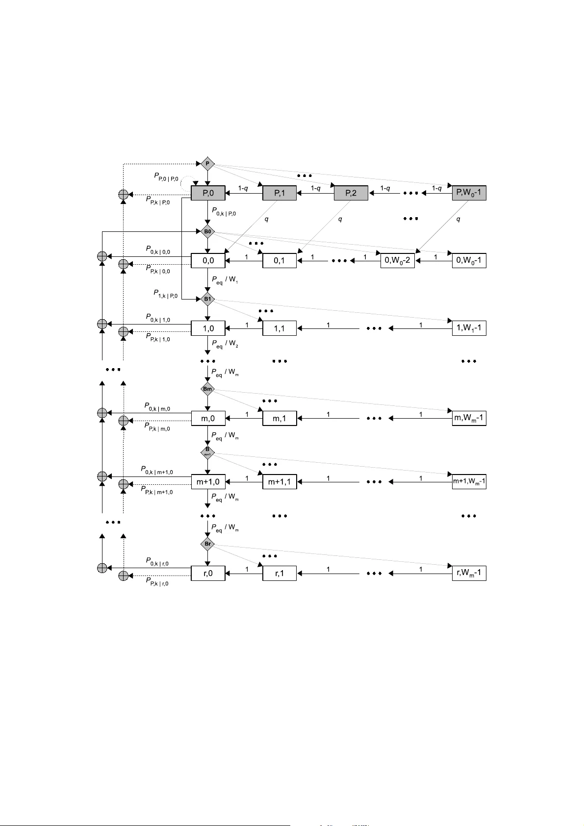
1 A No v el Proportional F airness Criterion for Throughp ut Allocation in Multirate IEEE 802.11 M. Laddomad a, F . Mesiti, M. Mondin, and F . Danes hgaran Abstract This paper focuses on multirate IEEE 802.11 Wireless LAN employing the mandatory Distributed C oordination Function (DCF) option. Its aim is threefold. Upon starting from the multi-dimensional Markov ian state transition model proposed by Malone et.al. for characterizing the behav ior of the IEEE 802.11 protocol at t he Medium Access C ontrol layer , it presents an extension accounting for pack et transmission failures due to channel errors. S econd, it establishes the conditions under which a network constituted by N stations, each station transmitting with i ts own bit rate, R ( s ) d , and packet rate, λ s , can be assumed loaded. Fi nally , it proposes a modified Proportional Fairness (PF ) criterion, suitable for mitigating the rate anomaly problem of multirate loaded IEEE 802.11 W ireless L ANs, employing the mandatory D CF option. Compared to the widely adopted assumption of saturated network, the proposed fairness criterion can be applied to general loaded networks. The throughput allocation resulting from the proposed algorithm is able to greatly increase the aggre gate throughput of t he DCF , while ensuring fairness lev els among the stations of the same order as the ones guaranteed by the classical PF cri terion. Simulation results are presented for some sample scenarios, confirming t he ef fectiv eness of the proposed criterion for optimized throughpu t all ocation. Index T erms DCF , Distributed Coordination Function, fairness, IEE E 802.11, MA C, multirate, non-saturated, proportional fairness, rate adaptation, saturation, throughput, traffic, unloaded, unsaturated. I . I N T R O D U C T I O N Consider the IEEE80 2.11 Mediu m Access Con trol (MA C) layer [ 1] employing th e DCF based on the Carrier Sen se Multiple Access Collision A voidance CSMA/CA access me thod. The scenar io en visaged in th is work conside rs N con tending station s; each station generates data packets with constant r ate λ s by emp loying a bit r ate, R ( s ) d , which depends on the chann el q uality experienced. In this scenario, it is known th at th e DCF is affected by the so-called performanc e anomaly problem [ 2]: in multirate networks the aggregate throu ghpu t is strongly influenced b y that o f th e slo west contending station. After the land mark work by Bianc hi [ 3], who provided an analysis of the satura tion throu ghput of th e basic 8 02.1 1 protocol assuming a two dimen sional Mar kov mo del at the MAC layer, many paper s have add ressed almost any facet of the b ehaviour of DCF in a variety of traffic loads and c hannel tr ansmission conditions. Contributions pro posed in the literatur e so far can be classified in two main classes, namely DCF Modelling and DCF Thr oughput a nd F airness Optimization . Massimilia no Laddomada is with the Electric al Engineering Dept. of T e xas A&M Univ ersity-T exark ana, email: mladdomada@t amut.edu. F . Mesiti and M. Mondin are with DELEN, Politecnico di T orino, Ital y . F . Daneshgar an is with ECE Dept., Calif ornia State Uni versit y , Los Angeles, USA. 2 DCF mo delling. This is the top ic that received the most attention in the liter ature since the work by Bianchi [3]. Papers [4]-[6] model the influen ce of real channel con ditions on the th rough put of the DCF operatin g in saturated traffic conditio ns, while [7]-[9] thorou ghly analyze the influe nce of ca pture o n the thr oughp ut o f wireless tran smission systems. Paper [1 0] inv estigates the saturation throughp ut of IEEE 802. 11 in presen ce o f non ideal transmission channel and cap ture ef fects. The behavior of the DCF of IEEE 802.1 1 WLANs in un saturated traffic conditio ns has b een analy zed in [11]-[18]. In [1 9], the autho rs look at the imp act of chann el indu ced errors and o f the received Signal-to-No ise Ratio (SNR) on the ach iev able throug hput in a system with r ate ad aptation, whereby the tra nsmission rate o f the termin al is mod ified depend ing on either dire ct or indir ect measuremen ts of the link qu ality . Multirate mode ling of the DCF has received some attentio n quite recently [ 20]-[24] as well. In [ 20] an ana lytical framework for analyzing the link delay of multirate networks is pr ovided. In [21]- [22], au thors provide DCF mo dels for finite load sou rces with m ultirate capabilities, while in [23]-[24] a DCF model for networks with m ultirate stations is provid ed and the saturation throug hput is derived. Remed ies to perf ormance anom alies are also discussed. I n b oth previous work s, pa cket erro rs are only due to c ollisions a mong the co ntendin g stations. DCF thr o ughp ut and fairness o ptimization. This is perhaps th e issue m ost closely r elated to the problem de alt with in this pap er . The main reaso n for optimizing the th rough put allocation of th e 802. 11 DCF is the behaviour of the basic DCF in h eterogen eous condition s, with stations transmitting at multiple rates: the sam e th rough put is reserved to any con tending station irrespe ctiv e of its bit ra te, with the undesire d con sequence that lo w est bit rate station s occupy the channel for m ost time with respect to high rate station s [25]. Fu rthermo re, the optimization of th e ag gregate th roug hput wh en different stations co ntend for the chann el with different bit rates canno t be don e without co nsidering an app ropriate fairness appr oach; the reason is that the op timum throug hput would b e achieved when o nly the highest rate stations acc ess the channel [25]. In ord er to face this problem , a variety of thr ough put optimization techniqu es, which accoun t for fairne ss issues, have been propo sed in the literature . Paper [25] propo ses a pro portion al fairness through put allocation criterion f or m ultirate and saturated IEEE 802.1 1 DCF by focu sing on the 802.1 1e stan dard. In papers [2 6]-[29] the authors pr opose novel fairness cr iteria, which fall within th e class of th e time-based fairness cr iterion. T im e-based fairness gu arantees equal time-share o f the c hannel occupa ncy irrespective to th e station bit rate. Paper [30] in vestigates th e fairness issue in 802.1 1 multirate n etworks by ana lyzing various time-b ased fairness criteria. It dem onstrates that with equal time- share of th e ch annel occupa ncy amo ng mu ltirate stations, the thro ughpu t ach iev ed by a referenc e station in a multirate scenario with N c ontendin g stations is eq ual to the th rough put that the same reference station would achieve in a single ra te scenario when con tending with other N − 1 stations with its same rate. Furth ermore , the author s prove that the p ropor tional fairne ss cr iterion co rrespon ds to fair chann el time allocation in a multirate scenario. The effect of the c ontention window size on the perfo rmance of the DCF ha ve been also in vestigated in [31]-[3 3] in a variety of d ifferent scenarios. Finally , papers [34]-[3 9] have been devoted to the throug hput optim ization of th e un derlined DCF by optimizing a n umber of key p arameters o f the DCF , such as the min imum co ntention window size or the p acket size. A commo n hy pothesis em ployed in th e literatu re regard s th e satu ration assum ption, which sometimes does n ot fit qu ite well to real n etwork traffic conditio ns. I n real networks, traffic is mostly non- saturated, different station s usually operate with different lo ads, i.e., th ey have different pac ket r ates, while the tr ansmitting bit rate ca n also dif f er among the co ntendin g stations. Chann el con ditions are far from being ideal an d o ften packet transmission has to be rescheduled until the data is correctly rec eiv ed. Due to Rayleig h and shadow fading conditio ns, a r eal scenario presents stations tr ansmitting at different bit 3 rates, because o f m ultirate ad aptation f oreseen at th e ph ysical layer of WLAN proto cols such as IEEE 802. 11b. In a ll th ese situations the commo n hypo thesis, wid ely emp loyed in the literatu re, tha t all the con tending stations have the same prob ability of transmitting in a random ly chosen time slot, d oes n ot h old anymore. The aim of this pa per is to in vestigate the beh aviour of th e DCF in the most general scenario of a multirate network, when all the previous effects act jo intly , as well as to p resent a prop ortional fairness cr iterion which accoun ts for gen eral loadin g condition s as exemplified by the p acket rate λ s of the conte nding stations. Contrary to th e af oremen tioned work s av ailab le in the literatur e, we assume that the s -th station gener ates data packets with its own size, P L ( s ) , with its own constant rate λ s by employing a b it rate, R ( s ) d , which depends on the chann el q uality experienced , and it employs a minimum conten tion wind ow with size W ( s ) 0 . Mo reover , each station is in a p roper load c ondition , which is independen t from the lo ading con ditions of the other contend ing stations. N otice th at these hy potheses make th e mo del p roposed in this work quite different from the o nes av ailable in the literature, where the saturated condition is mostly ad opted. One consequen ce of the proposed analysis is that unloade d, heterog eneous networks do n ot need a ny throu ghpu t allo cation am ong stations. W e p ropo se a theoretical framework in or der to identify wh ether a tagged station is satur ated, given the tra ffic co nditions of the rem aining stations. As a starting point for the deriv atio ns th at follow , we consider th e bi-dimensio nal Markov model p roposed in [12], and present the necessary modification s in ord er to deal with multirate stations, non ideal tran smission channel conditio ns, and different packet sizes among the c ontend ing stations. The rest of th e paper is organized as follows. Section II provides the necessary modificatio ns to the Markov model propo sed in [12], while the emp loyed traffic model is discussed in Section II -D. Section III p roposes an analytical fram ew o rk able to verify wh ether a ne twork o f N contend ing stations is loaded. Th e novel pr oportio nal fairness criterio n is p resented in Section IV, while Section V pre sents simulatio n results o f so me sample network scenar ios. Fin ally , Section VI d raws the conclusion s. I I . T H E N E T W O R K S C E N A R I O : O V E RV I E W O F T H E M A R K OV I A N M O D E L C H A R A C T E R I Z I N G T H E D C F In [ 12], the author s derived a bi-d imensional Markov mo del f or char acterizing th e beh avior of th e DCF in heterogen eous networks, where each station has its own tr affic, which could b e finite and c haracterized by the para meter λ , exp ressing the packet arriv al rate. I n ord er to deal with n on-satur ated co ndition s, th e traffic model is described by an exponen tially d istributed packet inter-arri val pro cess. In this paper we consider a m ore general network than [12]. Indeed, in the in vestigated network , each station employs a specific bit rate, R ( s ) d , a specific transm ission packet rate, λ s , tr ansmits p ackets with size P L ( s ) , an d it employs a minimu m contention win dow with size W ( s ) 0 , which can dif fer f rom the on e specified in the I EEE 802. 11 stand ard [1] (these modificatio ns are at the very basis o f the prop ortional fairness cr iterion prop osed in Section IV). A finite retry limit is co nsidered in order to a void infinite nu mber of retries whe n bad chann el cond itions inhibit th e station fr om succ essful transmission. For the sake of greatly simplifyin g the ev alu ation of the expected time slots req uired by th e theoretical d eriv atio ns that follow , we con sider N c ≤ N classes of chan nel occup ancy dura tions 1 . First of all, given the pay load lengths an d the data rates of the N stations, the N c duration -classes are ar ranged in order o f d ecreasing du rations ide ntified by the in dex d ∈ { 1 , · · · , N c } , whereby d = 1 identifies the slowest class. Notice that in our setup a station is denoted fast if it has a short channel occupancy . 1 This assumption relies on the observati on that in actual networks some stations might tran smit data frames present ing the same channel occupanc y . As an instanc e, a station ST A1 transmitt ing a packe t of size 128 bytes at 1 Mbps occupies the channel for the same time of a station ST A2 transmitt ing a packe t of size 256 bytes at 2 Mbps. 4 Furthermo re, each station is identified by an index s ∈ { 1 , · · · , N } , and it belo ngs to a un ique d uration -class. In o rder to identify the class of a station s , we define N c subsets n ( d ) , each of them con taining th e indexes of the L d = | n ( d ) | stations within n ( d ) , with L d ≤ N , ∀ d an d P N c d =1 L d = N . As an example, n (3 ) = { 1 , 5 , 8 } mean s that statio ns 1, 5, an d 8 belong to the third duration-class identified by d = 3 , a nd L d = 3 . A. Bi-d imensional Contention Markov Mod el The modified bi-dimensional Markov mo del describing the con tention p rocess of the s - th station 2 in the network is shown in Fig. 1. Let us elabor ate. W e consider an overall n umber of r different backoff stages, starting from the zero-th stage. The maximu m Contention W ind ow (CW) size is W max = 2 m W ( s ) 0 , with m ≤ r , whereas the notation W i = min(2 m W ( s ) 0 , 2 i W ( s ) 0 ) is used to identify th e i -th co ntention wind ow size ( W ( s ) 0 is the m inimum co ntention window size of the s - th station ). No tice that after the m -th stage, the con tention window size is fixed to W max for the rem aining ( r − m ) stages, after which th e packet is dropp ed. An add itional backoff stag e, identified by ( P, − ) , with the same window size of the zero- th stage , is considered on top of the chain in order to account for the post-backoff stage e ntered by the station after a successful packet tr ansmission, or packet d rop [ 1]. Moreover , the state lab elled ( P, 0 ) in Fig. 1, is used for em ulating u nloaded tr affic cond itions. After th e post-bac koff stage, a station starts a new transm ission because a new packet is available in the queue, provided that the channe l is sen sed idle for DIFS second s. On the other hand, a new zer o-th stage backoff is employed if the channe l is sensed busy . No tice th at th e post-b ackoff stage is enter ed on ly if th e station h as no lo nger packets to transmit after a packet transmission; otherwise, a zero- th stage is starte d. Mo reover , if a new packet arrives du ring a post-b ackoff stage, the station moves into the zero-th stage, as dep icted in Fig. 1. In deed, backoff stages f rom 0 to r assume that the station ’ s qu eue contain s at least a packet waiting fo r transmission . A p acket transmission is attemp ted only in the states labelled ( i, 0) , ∀ i = 0 , . . . , r , as well as in the state ( P, 0) o nly if the re is a packet in th e qu eue and the chan nel is sensed idle fo r DIFS seco nds. In case of collision, or d ue to the fact that transmission is unsuccessful because o f channel err ors, the b ackoff stage is inc remented an d the station moves in the state ( i + 1 , k ) , where k = 0 , . . . , W i +1 − 1 , with u niform p robab ility P eq /W i +1 , whereb y P eq , i.e ., the p robab ility of equiv alent failed transmission , is defined as P eq = 1 − (1 − P e )(1 − P col ) = P col + P e − P e · P col . Probab ilities P col and P e are, respectively , the co llision and the packet error probabilities re lated to the s -th station. The transition prob abilities f or the gene ric s - th station’ s Markov p rocess in Fig. 1 could be separated as sum marized in what follows, depen ding on whether transitions start fro m standa rd backoff states or from p ost-backoff states. Backoff state tra nsitions P i,k | i,k +1 = 1 , k ∈ [0 , W ( s ) i − 2] , i ∈ [0 , r ] P P ,k | i, 0 = (1 − P eq )(1 − q ) W ( s ) 0 , k ∈ [0 , W ( s ) 0 − 1] , i ∈ [0 , r − 1] P 0 ,k | i, 0 = (1 − P eq ) q W ( s ) 0 , k ∈ [0 , W ( s ) 0 − 1] , i ∈ [0 , r − 1] P P ,k | r, 0 = (1 − q ) W ( s ) 0 , k ∈ [0 , W ( s ) 0 − 1] , P 0 ,k | r, 0 = q W ( s ) 0 , k ∈ [0 , W ( s ) 0 − 1] . (1) The m eaning o f th e un derlined pr obabilities is as follows. The fir st eq uation in (1) states that, at the beginning of each slot time, the bac koff time is decremen ted. Th e second (thir d) equation accounts for the fact that after a successful transmission , the station goes in post-backoff because of an empty (no n e mpty) queue. In both equations, q is used to identify the prob ability 2 In order to kee p the nota tion concise, we omit the ape x s ove r the probabiliti es in volv ed in the model. 5 τ s = q 2 (1 − P r +1 eq ) W 0 · b P , 0 b P , 0 = n W 0 ( W 0 +1) 2 ( X B + X P ) − “ qW 0 − (1 − q )[1 − (1 − q ) W 0 ] q 2 ” X P + q W 0 qP eq K +(1 − q ) [1 − (1 − q ) W 0 ](1 − q ) o − 1 K = 1 2 » 2 W 0 1 − (2 P eq ) m − 1 1 − 2 P eq + 1 − P m − 1 eq 1 − P eq – + ( W m + 1) P m − 1 eq 1 − P r − m +1 eq 1 − P eq X B = q W 0 q 2 +(1 − P i )[1 − (1 − q ) W 0 ](1 − q ) W 0 [1 − (1 − q ) W 0 ](1 − q ) X P = q 2 1 − (1 − q ) W 0 (3) that the queue contains at least a packet waiting for tr ansmission after a time slot, and it will b e better d efined in Sec tion II-D, where the em ployed traffic model is described . The fo urth equation deals with th e situation in which th e station h as reached the retry limit and, a fter a packet transmission , the b uffer of the station is empty . In this situation, the station moves in th e p ost-backoff stage with an empty qu eue. Th e last equation accou nts for a scen ario similar to the previous o ne with the difference that, after th e packet tran smission, the queu e is not empty . Post-backoff st ate transitio ns P P ,k | P ,k +1 = (1 − q ) k ∈ [0 , W ( s ) 0 − 2] P 0 ,k | P ,k +1 = q k ∈ [0 , W ( s ) 0 − 2] P P , 0 | P, 0 = (1 − q ) P P ,k | P , 0 = qP i (1 − P eq )(1 − q ) W ( s ) 0 k ∈ [0 , W ( s ) 0 − 1] P 0 ,k | P , 0 = q (1 − P i )+ qP i (1 − P eq ) W ( s ) 0 k ∈ [1 , W ( s ) 0 − 1] P 1 ,k | P , 0 = qP i P eq W ( s ) 1 k ∈ [1 , W ( s ) 1 − 1] (2) The meaning of th e u nderlin ed prob abilities is as f ollows. The first equ ation states that the station rem ains in the post-backoff stage b ecause th e q ueue is empty , where as the second equation ac counts f or a transition in th e ze ro-th backoff stage beca use a new packet a rrives at th e en d of a backoff slot. The third e quation mo dels the situation in wh ich there are no packets waiting for transmission, and the station remains in the state ( P, 0) (idle state). The fourth equatio n dea ls with the situation in which the station is in the id le state ( P , 0 ) , and, at the end o f a backoff slot, a ne w p acket arr iv es in the q ueue. I n th is scenario, the packet is successfully transmitted, the qu eue is empty , and the station moves in anoth er po st-backoff stage. The term P i identifies the probab ility that the channel is idle, an d it is d efined as follows with respect to the s -th tagged statio n: P ( s ) i = N Y j =1 ,j 6 = s (1 − τ j ) The fifth equatio n accoun ts for a scenar io similar to the pr evious one, except th at the station queue is n ot empty after the immediate tr ansmission of a packet or a situation of busy chan nel. The last equation mod els th e scena rio in wh ich the station goes from the idle state ( P, 0) to the first backoff stage because of a failure o f the immediate transmission of the p acket a rrived in the he ad o f the q ueue. B. Thr o ughp ut Evalu ation Next line o f pursuit consists in finding the p robab ility τ s that the s -th station starts a transmission in a ran domly chosen time slot. Due to the lengthy algeb ra inv olved in the d eriv a tions needed for solving the b idimension al Mar kov chain, the relation that defines τ s has been d erived in an additional document available at [40], whereas for conciseness we show the final f ormula in ( 3) (shown at the bottom o f this page), along with th e o ther key probab ilities need ed in this paper . Gi ven τ s in (3), we can 6 ev aluate the a ggregate throu ghpu t S as follows: S = N X s =1 S s = N X s =1 1 T av P ( s ) s · (1 − P ( s ) e ) · P L ( s ) (4) whereby T av is the expected time per slot, P L ( s ) is the pac ket size of the s - th station, and P ( s ) s is the pr obability of successful packet tra nsmission of the s -th station: P ( s ) s = τ s · N Y j =1 j 6 = s (1 − τ j ) (5) The e valuation of the aggr egate thr ough put in (4) requir es the knowledge of the expe cted time per slo t, T av . Its evaluation is the focus of the next section . C. Eva luation of the Expected T ime per Slot The exp ected time per slot, T av , can be evaluated b y we ighting th e times spent by a station in a p articular state with the probab ility o f being in th at state. First of all, we o bserve th at there are four different kinds of time slots, with four different av erage durations: • th e idle slot, in which no station is transmitting over the chann el, with a verage duration T I ; • th e collision slot, in which more th an o ne station is attemptin g to gain ac cess to the channe l, with av erage d uration T C ; • th e slot d ue to erron eous tran smissions b ecause of imp erfect cha nnel con ditions, with average dur ation T E ; • th e successful tran smission slo t, with average duratio n T S . The expected time per slot, T av , can be ev alu ated by adding the four expected slot du rations: T av = T I + T C + T S + T E . (6) W e will n ow ev alua te T I , T C , T S , and T E . Upon id entifying with σ an idle slot du ration, and d efining with P T R the probab ility that the c hannel is busy in a slot because at least one station is tra nsmitting: P T R = 1 − N Y s =1 (1 − τ s ) (7) the a verage idle slot duration ca n be evaluated as follows : T I = (1 − P T R ) · σ (8) The average slot duratio n o f a succ essful transmission, T S , can b e fo und upo n averaging the prob ability P ( s ) s that on ly the s -th tagged station is successfully tr ansmitting over the chan nel, times the d uration T ( s ) S of a successful tr ansmission fr om the s -th station: T S = N X s =1 P ( s ) s “ 1 − P ( s ) e ” · T ( s ) S (9) Notice that the term (1 − P ( s ) e ) accounts f or the p robab ility o f p acket tran smission w ithout channel ind uced er rors. Analogou sly , th e a verage du ration o f th e slot due to erroneo us tra nsmissions c an be evaluated as follows: T E = N X s =1 P ( s ) s · P ( s ) e · T ( s ) E (10) Let us focus on the ev aluatio n o f the expe cted co llision slot, T C . The re are N c different values of th e collision probab ility P ( d ) C , dependin g o n th e class of th e tagged station iden tified b y d . W e assume that in a c ollision o f d uration T ( d ) C (class- d 7 collisions), only the stations b elongin g to the same class, or to high er classes ( i.e., stations who se ch annel occup ancy is lower than the one of stations belongin g to the tagg ed station indexed by d ) might be inv o lved. In order to identify the collision prob ability P ( d ) C , let us first define the following thre e transmission probabilities ( P C ( d ) T R , P H ( d ) T R , P L ( d ) T R ) u nder the hypothe sis that th e tag ged station belongs to the class d . Probability P L ( d ) T R represents the probability that at least another station belo nging to a lower class transmits, and it can be evaluated as P L ( d ) T R = 1 − d − 1 Y i =1 Y s ∈ n ( i ) (1 − τ s ) (11) Probability P H ( d ) T R is th e probability tha t at least one station b elonging to a highe r class transmits, and it can be e valuated as P H ( d ) T R = 1 − N c Y i = d +1 Y s ∈ n ( i ) (1 − τ s ) (12) Probability P C ( d ) T R represents th e probability that at least a station in the same class d transmits: P C ( d ) T R = 1 − Y s ∈ n ( d ) (1 − τ s ) (13) Therefo re, the co llision probab ility for a gener ic class d takes into accoun t only co llisions between at least on e station of class d and at least one station within the same class (interna l collision s) or be longing to higher class ( external collision s). Hen ce, the total collision pr obability can be ev aluate d as: P ( d ) C = P I ( d ) C + P E ( d ) C (14) whereby P I ( d ) C = (1 − P H ( d ) T R ) · (1 − P L ( d ) T R ) · (15) · P C ( d ) T R − X s ∈ n ( d ) τ s Y j ∈ n ( d ) ,j 6 = s (1 − τ j ) represents the inter nal collisions between at least two stations within th e same class d , while the r emaining are silent, and P E ( d ) C = P C ( d ) T R · P H ( d ) T R · (1 − P L ( d ) T R ) (16) concern s to the external collisions with a t least on e station of class higher than d . Finally , th e expec ted dur ation of a collision slot is: T C = N c X d =1 P ( d ) C · T ( d ) C (17) Constant time durations T ( s ) S , T ( s ) E and T ( d ) C are d efined in a m anner similar to [22] with the slight difference that the first two dur ations are associated to a gen eric station s , wh ile the latter is associated to each d uration class, which depen ds on the combinatio n of both p ayload length an d data rate of the station of class d . D. T raffic Mod el The employed tr affic model for each station assumes a Poisson distributed packet arriv al process, whereby th e inter-arri val times amon g packets are exponentially distributed with mean 1 / λ t . In or der to greatly simplify the analysis, we co nsider small queue, as propo sed in [ 12], ev en th ough the propo sed an alysis may be easily extended to q ueues with any len gth. The traffic of each station is acco unted for with in th e Markov mode l by employin g a pro bability 3 , q , that accou nts f or the scenario whereby 3 A superscript ( t ) is used for disc erning the probabi lity q among the stations. 8 at least o ne packet is available in th e queu e at the end o f a slot. I n our setting, each station is characterized by its own tr affic, and the pro bability q ( t ) of the t -th station can be ev aluated b y averaging over th e four types of time slots, namely idle, success, collision, an d channel erro r time slot. Upon no ticing that, with the underlin ed pac ket model, the p robab ility of ha ving at least one packet arrival d uring time T is equa l to 1 − e − λ t · T , q ( t ) can be evaluated as: q ( t ) = (1 − P T R ) · (1 − e − λ t · σ )+ + P N s =1 P ( s ) s 1 − P ( s ) e · (1 − e − λ t · T ( s ) S )+ + P N s =1 P ( s ) s · P ( s ) e · (1 − e − λ t · T ( s ) E )+ + P N c d =1 P ( d ) C · (1 − e − λ t · T ( d ) C ) (18) whereby the p robab ilities P T R , P ( s ) s , and P ( d ) C are, r espectively , as defined in ( 7), (5), an d (14), wherea s P ( s ) e is th e packet error rate o f th e s -th station . I I I . E V A L UAT I N G T H E N E T W O R K L O A D I N G C O N D I T I O N S In a pre vious paper [1 4], we proved th at the beha viour of the aggregate throu ghput in a network of N homo geneou s 4 contend ing stations is a linear function of the p acket arriv al rate λ with a slope d epend ing on both the num ber of contendin g stations and the average payload len gth. W e also derived the in terval of validity o f th e proposed m odel by showing the presence of a critical λ , above which all th e stations begin operating in saturated traffic cond itions. This kind o f b ehaviour , with ap prop riate generalization s, is also ob served when m ultirate a nd variable loaded stations ar e present in the network. W e have to identify a set of co nditions fo r a ne twork to be conside red as loaded . W e no tice in pa ssing that this f ramework is not generally con sidered in the literatur e, sinc e most papers assume saturate d tr affic condition s. A key observation fro m th e an alysis de veloped in this section is that in an unload ed network there is no need to guarantee fairness, since each co ntendin g stations can transmit its packets at its own p ace, regardless of its m inimum CW , as well as o ther network parameters. Under the traffic model d escribed in section II-D, we define unloaded a network in which each conten ding station has a packet ra te λ t less than o r equal to its packet service rate ˜ µ ( t ) S : λ t ≤ ˜ µ ( t ) S , ∀ t ∈ { 1 , . . . , N } (19) The reason is simple: this co ndition ensur es that the av erage packet inter-arriv al time is gr eater than or equ al to the av erage service time of the t - th station . In such a scenario, the probabilities of collisions amon g stations are very low , an d each contend ing station is able, on the average, to g ain the acc ess to the channel as soon as a ne w packet arri ves in its q ueue. Notice that ˜ µ ( t ) S only depends o n th e p acket rates λ i of the o ther N − 1 stations oth er than the tagged one. The ev aluation of the packet service rate ˜ µ ( t ) S in a multirate and heter ogeneo us network is quite difficult [12] since packet arriv als may o ccur during the stage of post-b ackoff, as well as dur ing the usual backoff stages accom plished by each station before gaining th e c hannel for tra nsmission. Sinc e w e are interested in a threshold wh ich differentiates the unsaturated f rom the saturated loading co nditions of the stations, we can e mploy an upper bound defined by the satu ration service rate, identified as µ ( t ) S , in place of the actual service r ate ˜ µ ( t ) S . Th e advantage r elies on the observation that such a bou nd is always evaluated considerin g a po st-backoff stage. Indeed, af ter a packet transmission , a ne w pa cket is al ways av ailable in the queue assum ing saturated tr affic; therefor e, the service time starts from a post-backoff p hase w hereby the contentio n window is W ( s ) 0 . W e 4 By homogeneous we simply mean that the network is characteriz ed by N stations transmitti ng with the same bit rate (no multirate hypothesis) and the same load . 9 notice th at the saturation serv ice time always includes th e post-b ackoff stage, thus its dura tion is lon ger than the actu al service time e valuated without considering th e post-backoff time. Hence, in th e rem aining part of th is section, we ev aluate the saturation service rate µ ( t ) S = 1 /T ( t ) serv , i.e., the rate at which packets are taken from the qu eue of the t -th station u nder satu rated conditions. Upon considerin g the tagged station identified by the index t ∈ { 1 , · · · , N } , the satur ation service time T ( t ) serv can be defined as follows [28]: T ( t ) serv = n P r i =0 ( P ( t ) eq ) i “ iT C + P i j =0 W ( t ) j · T ( t ) bo + T ( t ) S ” + ( P ( t ) eq ) r +1 ( r + 1) T C + r X j =0 W ( t ) j · T ( t ) bo ! | {z } D RO P 9 > > > > = > > > > ; / P r +1 j =0 ( P ( t ) eq ) j (20) The first ter m in the summation repr esents the average time that a station spends throu gh the backoff stages from 0 to r befo re transmitting a packet, i.e., the so called MAC access time. W e notice th at for the i -th stage, i co llisions of average duration T C , as well as i backoff stages fr om 0 to i (eac h of them with an average number W ( t ) j of slot o f d uration T ( t ) bo ) oc curred, after which the p acket is succe ssfully tra nsmitted w ith duratio n T ( t ) s . The second term of the su mmation takes into account the a verage duration o f a packet d rop that occurs af ter ( r + 1) collisions and backoff stages. The whole sum mation is scaled by a n ormalization factor that takes into accoun t the proba bility set over which the service time is evaluated. The a verag e n umber of slots for the i backoff stages, is defined as W ( t ) j = (2 min( j,m ) · W ( t ) 0 − 1) / 2 . Each slo t h as average duration T ( t ) bo , which is substantially ev aluated as T av in (6) except that the tagged station ( t ) is no t considered because it is either idle, o r in a backoff state. Let us discu ss two sample scenario s in order to derive a variety of o bservations that are at the very basis o f the fairness problem d ev eloped in the next section. The network par ameters u sed in the inv estigated IEEE8 02.11 b MAC layer a re r eported in T able I [ 1]. The first in vestigated scen ario considers a network of 3 conten ding stations. T wo station s, namely S2 and S3, transmit packets with constant rates λ = 100 pkt/s and λ = 500 pkt/s, respectively . Th e bit rate of the two stations S2 an d S3 is 11 Mbps. The third station , S1, has a bit rate equa l to 1 Mbps a nd a packet rate λ 1 that is varied in the rang e [0 , 2000] pkt/s in ord er to in vestigate its effects on the ne twork load. Th e beh aviour o f the three ratios λ t /µ ( t ) S is shown in Fig. 2. Some observations are in o rder . First of all, notice th at as far as S1 incr eases its packet rate, th e curves λ 2 · T (2) serv and λ 3 · T (3) serv tend to incr ease because o f th e increasing values of the serv ice times T (2) serv and T (3) serv experienced by S2 and S3. Notice that, as λ 1 increases, the slowest station S1 ten ds to tran smit m ore often. The station S3 g oes in lo aded co ndition when λ 1 ≈ 20 pkt/s, while S2 can be co nsidered loaded for λ 1 ≈ 200 pkt/s. When a station beco mes lo aded, the inc oming packets tend to be stored in the station queu e waiting for transmission since the service rate , i.e ., the n umber of packets tha t on average are serviced by the MA C, is below th e r ate by wh ich th e p ackets arrive in the station qu eue. The p er-station throu ghpu t achieved by the th ree station s in the in vestigated scenario is shown in Fig. 3. T he throu ghpu t gained by the two fastest station s, S2 and S3, tends to decrease beca use of the ano maly prob lem in the multir ate scenario: the slowest station tends to occu py the chann el lon ger and longer as far as its p acket rate λ 1 increases. In th e same figure, we show two tick cur ves. The horizontal line L2 correspond s to the satu ration th rough put o f S1 , wh ile the straigh t line L1 is the tangent to the through put curve passing through the o rigin. For very small values o f λ 1 , the throug hput of the station S1 grows linearly with λ 1 . Packets are mainly tr ansmitted as soon a s they arriv e at the MA C layer , and the station thr ough put is 10 approx imately eq ual to λ 1 · P L (1) . H owe ver, when th e station approac hes the transition point λ ∗ 1 = 89 . 19 pkt/s derived with the propo sed f ramework (this is the value of λ 1 correspo nding to th e relation λ 1 /µ (1) S = 1 ), the th rough put curve tends to reach the a symptote L 2, which correspo nds to the saturation through put o f S1 . Notice that the curve L2 approx imately co rrespon ds to 0.73 Mb ps, wh ich is λ ∗ 1 · P L (1) = 89 . 19 · 1 028 · 8 bps. In the second scenario, the stations S1 and S2 are interested by a constant p acket rate noticed in the label of Fig. 4 . T hese two stations do not get loa ded b y the incre asing packet rate of the station S3 since the cur ves λ 1 /µ (1) S and λ 2 /µ (2) S are strictly less than one. As a consequ ence, the per-station through put of both S1 and S2 is approxim ately con stant acr oss the range of values o f the packet rate λ 3 as noticed in Fig. 5. On the other han d, the through put ac hieved by the station S3 tends to satu rate as soon as λ 3 reaches the v a lue 5 33 p kt/s noticed in Fig. 4. In the light of the p revious two samp le scena rio, let u s summ arize the main ing redients o f the r esults pr oposed in this section. As obser ved in the two previous sample scenar ios, this me thod allows to iden tify whether th e network is loade d by establishing the threshold s of each contend ing station in the network. This issue has been overlooked in the literature, where the saturation assump tion is widely adopted. Moreover , this issue is at the very basis of any through put op timization stra tegy since an un loaded network does not n eed to b e o ptimized. W e say that the network is load ed when every station has a traf fic ab ove its pr oper thresh old. On the other h and, it sho uld be notice d th at a network can b e unloa ded even if a subset of the stations is lo aded. This was the case of th e second scenario described above, where, d espite th e fact th at the station S3 was interested by an inc reasing traffic load λ 3 , the station s S1 and S2 did n ot expe rience any performanc e lo ss ( see Fig. 5) becau se their traffics were below the respectiv e thresho lds. I V . T H E P RO P O RT I O N A L F A I R N E S S T H R O U G H P U T A L L O C A T I O N A L G O R I T H M This section presents the novel throug hput allocation criterion , wh ich aims at improving fairness among the N con tending stations. In ord er to face the fairness pr oblem in th e most gen eral scenario , i.e., multirate DCF and general station loading condition s, we propo se a novel Propo rtional Fairness Criterio n ( PFC) by starting from the PCF defined by K e lly in [41], and employed in [2 5] in conn ection to prop ortional fairness throughp ut allocatio n in multirate and saturated DCF opera tions. It is known that on e of the main drawbacks of the basic D CF operating in a multir ate scenar io relies on the fact that it behaves in such a way as to gu arantee equ al long-term chan nel access prob ability to the various conten ding stations [25], [30]. In ord er to so lve this pro blem, various o ptimization algorithm s have been prop osed in the literatur e (see, f or instance, [25]-[37]). These contr ibutions allo we d to high light the behaviour of the DCF a s we ll a s various d rawbacks when o perating in a multirate scenario. For instance, it is known that the aggregate thro ughp ut o f m ultirate IE EE802 .11-like n etworks is optim ized when only th e high rate station s transmit, while the low rate stations are kept silent. Of cou rse, this result is not desirable fr om a fairness po int of view , even tho ugh it mitigate s the DCF performa nce ano maly n oticed in [2] . T o the b est of our knowledge, th e solution s prop osed so far in the literatur e refer to homog eneous n etworks in that all the contend ing stations oper ate with the same traffic, as exemplified by th e station packet rate λ s , and chann el condition s. Furthermo re, almost all the work s fo cus on satur ated traffic cond itions. As alrea dy me ntioned befor e, in a pr actical setting th e contend ing stations hav e their own traffic and are affected b y d ifferent chann el conditio ns. The ke y o bservation here is that a fair thr oughp ut allocation should accoun t for the station packet r ate, as well a s for th e specific chann el cond itions experienced by each contending station . Let us briefly mentio n the rationales at the very basis o f th e PFC. A proportio nal fairness optimizatio n criter ion allocates to each station a thr oughp ut pr o portiona l to th e station transmission rate. Resorting to th e notation prop osed in [ 41], a thro ughp ut 11 allocation vector x = { x s ; s = 1 , · · · , N } is pr opo rtional fair if the following con dition holds: N X s =1 y ∗ s − x s x s ≤ 0 (21) for any other fea sible throu ghpu t allocation vector y ∗ . T he PFC max imization problem , which satisfies (21), can be fo rmalized as follows : max N X s =1 log( x s ) (22) over x s ∈ [0 , x s,m ] , s = 1 , . . . , N whereby x s,m is the ma ximum throug hput of the s -th station. Du e to the stric t concavity of the log arithmic function and because of the co mpactness of the feasible region x s ∈ [0 , x s,m ] , s = 1 , . . . , N , there exists a uniq ue solution to th e optimization problem (22). Th is implies that a local m aximum is also global. Giv en these preliminar ies, in the pr oposed mod el, the traffic of each station is cha racterized by th e pa cket arriv al r ate λ s , which depends ma inly on the applica tion layer . Let λ max be th e maximum packet r ate among λ 1 , . . . , λ N . Consider the following mod ified o ptimization problem: max U = U ( S 1 , · · · , S N ) = P N s =1 λ s λ max · lo g( S s ) subject to S s ∈ [0 , S s,m ] , s = 1 , . . . , N (23) whereby S s is the throug hput of th e s -th station, a nd S s,m is its maximum value, which equals the station bit ra te R ( s ) d . In our scen ario, the ind ividual thro ughp uts, S s , ar e interlaced be cause of the interdepen dence of the prob abilities inv olved in the transmission proba bilities τ s , ∀ s = 1 , . . . , N . For this r eason, we reform ulate the maximizatio n pro blem in or der to fin d the N optimal values of τ s for wh ich the co st functio n U in (23) ge ts maxim ized. Th e optim al values τ ∗ s are then used to set the network parameters of each station. Due to the co mpactness o f the feasible region S s ∈ [0 , S s,m ] , ∀ s , the m aximum o f U ( S 1 , · · · , S N ) can be fo und among the solutions of ∇ U = ∂ U ∂ τ 1 , · · · , ∂ U ∂ τ N = 0 . After some algebra (th e d eriv atio ns are r eported in the App endix) , the solution s can be written a s: λ j λ max 1 τ j − 1 1 − τ j N X k =1 ,k 6 = j λ k λ max = C T av ∂ T av ∂ τ j , ∀ j = 1 , . . . , N (24) whereby C = P N i =1 λ i λ max , and T av is a fu nction o f τ 1 , · · · , τ N as noticed in (6). Due to the presen ce of T av , a closed fo rm of the m aximum o f U ( S 1 , · · · , S N ) can not b e fou nd. Notice that it is quite difficult to de riv e th e c ontribution of th e partial d eriv ative of T av on τ j , especially when N ≫ 1 , b ecause of the hu ge numb er of network param eters b elongin g to different station s. Th e definition of T av in (6) is com posed by four different terms, which include the whole set of τ s , ∀ s . In o rder to overcom e this p roblem, we first numer ically obta in the optim al values τ ∗ s , ∀ s f rom (24), then, we choose the value of the minimum contention window size, W ( s ) 0 , b y eq uating the optim izing τ ∗ s to ( 3) for any s . The op timization criterion summ arized in ( 23) will b e de noted as L oad Propor tional Fairness (LPF) criterion in the fo llowing. Let us derive so me observations on the proposed throughp ut allocation algorithm by contrasting it to the classical PF algorithm . Conside r two con tending stations with packet r ates λ 1 = 50 pkt/s and λ 2 = 10 0 p kt/s, respectively . Employin g the c lassical PF m ethod, a through put allocation is prop ortionally fair if a r eduction of x % of th e thr ough put allocated to o ne station is co unterb alanced b y an in crease of mo re th an x % of the throughp uts allocated to the other contending station s. 12 In our setup, the ratio λ 1 /λ 2 can be interpreted as the freq uency by which the first station tries to g et ac cess to the chan nel relativ e to th e o ther station . Therefo re, a thro ughpu t a llocation is p ropo rtionally fair if, fo r instance, a reduction of 20 % o f th e throug hput allocated to th e first station, which has a relative f requen cy o f 1 / 2 , is counter balanced by an increase o f mo re than 40% of the th rough put allocated to the second statio n. In a scenario with mu ltiple co ntendin g stations, the relati ve frequency is e valuated with respect to the station with th e h ighest packet rate in the n etwork, that gets unitary relati ve frequen cy . Based on extensive analysis, we found that the optimiza tion problem (23) som etimes yields throu ghput allocations that cannot be actually ma naged by the stations. As a reference example, a ssume that, due to the specific chann el cond itions experienced , the first station has a b it rate eq ual to 1 Mb ps and needs to transmits 200 pk t/s. G i ven a packet size o f 102 4 by tes, that is 8192 bits, the first station would need to transmit 819 2 × 200 bps ≈ 1 . 64 Mbp s far above the maximum bit rate decided at the physical layer . In this scenar io, such a station co uld n ot send over the channel a throu ghpu t greate r than 1M bps. Th e same applies to th e other co ntendin g stations in the n etwork experienc ing similar co nditions. I n or der to face this issue, we considered the fo llowing o ptimization problem max P N s =1 λ ∗ s λ ∗ max · lo g( S s ) over S s ∈ [0 , S s,m ] , s = 1 , . . . , N (25) where ∀ s = 1 , . . . , N , λ ∗ s = λ s , if λ s · P L ( s ) · 8 ≤ R ( s ) d R ( s ) d 8 · P L ( s ) , if λ s · P L ( s ) · 8 > R ( s ) d and λ ∗ max = max s λ ∗ s . T he allocatio n prob lem in (25), solved as fo r the LPF in (23), guaran tees a thro ughp ut allo cation which is p ropo rtional to the freq uency of channel acce ss o f e ach station relative to their actual a bility in manag ing such traffic. T he idea relies on the observation that it is n ot o ptimal to allocate a throughp ut that th e station can not actually ma nage. The o ptimization criterio n summar ized in ( 25) will be den oted as Modified Loa d Pro portion al Fairness (MLPF) criterion in what follows. As in the case of the LPF criterion, th e MLPF optimizatio n prob lem in (25) is solved by first num erically obtaining the op timal values τ ∗ s , ∀ s , and then choosing the value of the minim um con tention w indow sizes W ( s ) 0 by equating the optimizing τ ∗ s to ( 3) independen tly f or any s . V . S I M U L AT I O N R E S U LT S This section presents simulation r esults obtained fo r a variety of network scen arios optim ized with the fairness criteria propo sed in the previous sectio n. W e hav e dev eloped a C++ simulato r modelling both the DCF p rotocol details in 8 02.11 b and the backoff procedur es of a specific numb er of in depend ent transmitting stations. The simulator con siders a n Infrastructu re BSS (Basic Serv ice Set) with an Access Poin t (AP) and a certain num ber of fix stations which comm unicate o nly with th e AP . Traf fic is genera ted f ollowing the exponential d istribution for the packet interarr iv al times. Moreover , the MA C layer is managed b y a state machine which follows the main directives specified in the standa rd [ 1], namely waiting times (DIFS, SIFS, EI FS), post-backoff, backoff, basic and R TS/CTS access mo des. The typical MA C layer para meters f or IEEE802. 11b repo rted in T a ble I [1] hav e been u sed for perfor mance validation. The first investigated scenario, namely scenario A, considers a network with 3 contend ing stations. T wo stations tran smit packets with rate λ = 500 pkt/s at 11 Mbps. The payload size, assumed to be co mmon to all the stations, is P L = 10 28 bytes. The thir d station ha s a bit rate equal to 1Mbp s and a packet rate λ = 100 0 pkt/s. 13 From (1 9), it is straightforward to notice that the scenario A refers to a loaded ne twork. Fig. 6 shows the service ra tes µ ( t ) S of the three contending station s as a fu nction of the p acket rate λ 1 of the station tr ansmitting at 1 M bps. The operatin g poin t of the co nsidered scenario A is hig hlighted in Fig. 6. N otice that, since th e service rates µ ( t ) S of the thr ee stations are below the r espective packet rates λ t , the network is loaded. Moreover, the service rates of th e th ree stations tend to the same v alues because of the rate anomaly problem: th e station tran smitting at 1 Mbps reduces th e serv ice rates of the other stations. The simulated normalized throughp ut achieved by each station in th is scenario is depicted in th e left subplot of Fig. 7 for the following f our setup s. Th e three bars labelled 1-DCF r epresent the normalized thr ough put ach iev ed by the three station s with a classical DCF . Th e second set o f b ars, labelled 2-PF , identifies th e simulated norm alized throug hput achieved by the DCF optimized with the PF criterion [2 5], [41], wher eby the actu al packet rates o f the stations are n ot consider ed. T he third set of bar s, labelled 3-L PF , represents the normalized th rough put achieved by th e thr ee stations wh en the allocation p roblem (2 3) is employed . Finally , the last set of bars, labe lled 4-MLPF , rep resents th e simulated norm alized th rough put achieved by the contend ing stations when the CW sizes are optimized with the m odified fairness c riterion in (25). Notice that th e through put allocations gu aranteed by LPF an d MLPF impr ove over the classical DCF . When the station pac ket rate is con sidered in the op timization f ramework, a high er throu ghpu t is allocated to the first station presenting the max imum value of λ among the consider ed stations. Howe ver, th e highest ag gregate thro ughp ut is ach iev ed when the allocatio n is accomp lished with the optimization framework 4-MLPF . The re ason f or this beh aviour is related to the fact that the first statio n requires a traffic equal to 8 . 22 M bps = 10 3 pkt/s · 1028 b ytes/pkt · 8 bits/pkt, which is far above the maximu m tr affic ( 1 Mbps) that the station would be able to deal with in th e best scenario. I n this respect, the MLPF criterio n results in b etter throu ghpu t allocations since it acc ounts for th e re al traffi c th at the con tending station would b e able to deal with in the specific scenario at ha nd. Similar consideration s can be drawn from the results shown in the right subplot of Fig. 7 (related to scenario B), wh ereby in the simulated scenar io the two fastest stations are also ch aracterized by a packet ra te greater than the on e of the slowest station. Notice th at the optimiz ation fr amework 3 -LPF is able to gu arantee improved agg regate thr ough put with respect to bo th the n on-o ptimized DCF and the c lassical PF algor ithms. The op erating po int of the scen ario B is high lighted in Fig . 6; based on the c onsideratio ns above, this is a loaded network as well. The aggregate throu ghpu ts achieved in the two investigated scenar ios ar e as fo llows: Scenarios 1-DCF 2-PF 3-LPF 4 -MLPF A Jain’ s Index 0.451 0.872 0.724 0.848 S [Mbps] 1.85 3.60 3.10 5.07 B Jain’ s Index 0.474 0.881 0.976 0.847 S [Mbps] 1.99 3.63 4.62 5.07 whereby we also show th e fairness Jain’ s index [4 2] ev aluated on the norm alized th rough puts no ted in the subplots of Fig. 7. It is worth noticing that the pro posed MLPF throug hput allocation c riterion is able to guarantee improved aggr egate thr ough put relativ e to both the classical DCF and the PF algorith m, with fairn ess levels o n the same o rder o f th e o nes guar anteed by the classical PF alg orithm. For the sake of in vestigating the beh aviour of the propo sed allocation criteria as a function of the p acket rate o f th e slowest station, we simulated the throughpu t allocated to a network composed by three stations, whereby the slo west station, transmitting 14 at 1 Mbps, pr esents an increasin g packet r ate in the r ange 1 0 − 300 0 pkt/s. T he o ther two stations tran smit p ackets at the con stant rate λ = 5 00 pkt/s at 1 1 Mbps. The simu lated throu ghpu t of the thr ee co ntending stations is shown in th e three subp lot o f Fig. 8 for the unop timized DCF , as well as fo r the two criteria LPF a nd ML PF . Som e c onsideration s ar e in ord er . Let us fo cus on th e thr oughp ut of th e DCF (u pperm ost subp lot in Fig. 8). As far as the packet rate o f the slo west station increases, the throug hput allocated to th e fastest stations decrea ses quite fast beca use o f the per forman ce anomaly of the DCF [2]. The three stations reach the same thro ughp ut when the slowest station presen ts a p acket rate equal to 500 pk t/s, c orrespon ding to the one of the o ther two station s. From λ = 5 00 pk t/s a ll the way up to 300 0 pkt/s, the throug hput of the three stations d o no t change anymor e, since all the stations h av e a through put imp osed by the slowest station in the network. Let us focu s on the results shown in th e other tw o sub plots of Fig . 8, labelled LPF and MLPF , respectively . A qu ick comparison among these three subplots in Fig. 8 reveals that the ML PF allo cation criter ion g uarantee s improved aggregate thro ughp ut f or a wide rang e of packet rates of th e slo west station, greatly mitigating the rate a nomaly problem o f the classical DCF o perating in a multirate setting. In terms of aggr egate th roug hput, the best solution is achieved with the MLPF cr iterion, which avoids that the slowest station receiv es a throug hput allocation that would not be ab le to emp loy du e to its reduced bit rate (1 Mbps). V I . C O N C L U S I O N S Focusing o n multirate IE EE 802.11 W ireless LAN employing the mandato ry Distributed Coordination Function (DCF) option, this paper estab lished th e con ditions un der which a n etwork constituted by a certain numb er of station s tr ansmitting with th eir own bit r ates and p acket rates can be con sidered loaded . It the n pro posed a modified pr oportio nal fairness criter ion suitable for mitig ating the rate anomaly p roblem of mu ltirate loaded IEEE 802.11 Wireless LANs. Simulation results we re presented fo r some sample scena rios showing that the prop osed throughp ut allocatio n was able to greatly increase the aggregate thro ughp ut o f the DCF , wh ile ensuring fairness levels amo ng the stations o f the same o rder of the ones available with the c lassical propor tional fairne ss criterion . R E F E R E N C E S [1] IEEE Standar d for W ir eless LAN Medium Access Contr ol (MAC ) and P hysical Layer (PHY) Speci fications , Novembe r 1997, P802.11 [2] M. Heusse, F . Rousseau , G. Berge r-Sabba tel, and A. Duda, “Performance anomaly of 802.11b” In Proc. of IEEE INFOCOM 2003 , pp. 836-843. [3] G. Bianchi , “Performanc e analysis of the IEEE 802.11 distribute d coordination function” , IEEE JSAC , V ol.18, No.3, March 2000. [4] H.C. Lee, “Impact of bit errors on the DCF throughput in wireless LAN ov er rice an fadi ng channels”, In P r oc. of IEEE ICDT ’06 , 2006. [5] Q. Ni, T . Li, T . Turle tti, and Y . Xiao, “Saturation throughput analysis of error-prone 802.11 wireless networks”, W ile y Journal of W irele ss Communicatio ns and Mobi le Computing , V ol. 5, No. 8, pp. 945-956, Dec. 2005. [6] P . Chatzi misios, A.C. Boucouva las, and V . V itsas, “Influe nce of cha nnel BER on IEEE 802.11 DCF”, IEE Electr onics Letters , V ol.39, No.23, pp.1687- 1689, Nov . 2003. [7] M. Zorzi and R.R. Rao, “Capture and retransmission control in mobile radio”, IEEE JSA C , V ol.12, No.8, pp.1289 - 1298, Oct. 1994. [8] J.H. Kim and J.K. Lee, “Capture ef fects of wireless CSMA/CA protocols in Raylei gh and shadow fadin g channe ls”, IEEE T rans. on V eh. T ech. , V ol.48, No.4, pp.1277-1 286, July 1999. [9] Z. Hadzi-V elkov and B. Spasenovski, “Capt ure effec t in IEEE 802.11 basic service area under influence of Rayleigh fadi ng and near/f ar effec t”, In Proc. of 13th IEE E International Symposium on P ersonal, Indoor and Mobile Radio Communicati ons , V ol.1, pp.172-176 , Sept. 2002. [10] F . Daneshgaran, M. Laddomada, F . Mesiti, M. Mondin, and M. Zanolo, “Saturation throughput analysis of IEEE 802.11 in presence of non ideal transmission channel and captu re effec ts, ” IEEE Trans. o n Communicati ons, V ol. 56, No. 7, pp.1178-11 88, July 2008,. [11] L.Y . Shyang, A. Dadej , and A.Jayasuri ya, “Performanc e analysis of IE EE 802.11 DCF under limited load”, In Proc. of A sia-P acific Confer ence on Communicat ions , V ol.1, pp.759-763, 03-05 Oct. 2005. [12] D. Malone, K. Duffy , and D.J. L eith, “Modeling the 802.11 distribute d coordinati on functio n in non-saturated heteroge neous conditions”, IEEE -ACM T rans. on Networking , vol. 15, No. 1, pp. 159172, Feb . 2007. 15 [13] F . Daneshg aran, M. Laddomada, F . Mesiti, and M. Mondin, “ A model of the IEEE 802.11 DCF in presence of non ideal transmission channe l and capture ef fects, ” In Proc. of IEEE Globec om 07, W ashington DC, Nov ember 2007. [14] F . Daneshgaran, M. Laddomada, F . Mesit i, and M. Mondin, “Unsaturated throughput analysis of IEEE 802.11 in presence of non ideal transmission channe l and capture ef fects, ” IEEE Trans. o n W ireless Communicat ions, V ol. 7, No. 4, pp. 1276-1286, April 2008. [15] W . Lee, C. W ang, and K. Sohraby , “On use of tradition al M/G/1 model for IEEE 802.11 DCF in unsaturat ed traf fic conditions” , In Pr oc. of IEEE WCNC , 2006, pp. 19331937. [16] H. Zhai, Y . Kwon, and Y . Fang, “Performance analysis of IEEE 802.11 MAC protoco ls in wireless L ANs, ” W ireless Communicat ions and Mobil e Computing, vol. 4, issue 8, pp. 917-931, Dec. 2004. [17] Y . Zheng, K. Lu, D. W u, and Y . Fang, “Performance anal ysis of IEEE 802.11 DCF in imperfe ct channel s, ” IEEE T ransactions on V ehicul ar T echnology , V ol. 55, No. 5, pp. 1648-1656, Sept. 2006. [18] F . Daneshgaran, M. L addomada, F . Mesiti, and M. Mondin, “On the linear behav iour of the throughput of IEE E 802.11 DCF in non-saturat ed condi tions”, IEEE Communica tions Letters , V ol. 11, No. 11, pp. 856-858, Nov . 2007. [19] D. Qiao, S. Choi, and K.G. Shin, “Good put ana lysis and lin k adapt ation for IEE E 802.11a wireless LANs”, IEEE T rans. On Mobil e Computing , V ol.1, No.4, Oct.-Dec . 2002. [20] T . Joshi, A. Mukherjee, and D.P . Agrawal, “ Analytic al modeling of the link delay characte ristics for IEEE 802.11 DCF multi-rate WLANs, ” In Proc. of IEEE CCECE-CCGEI , pp. 2164-2167, May 2006. [21] G.R. Cantieni, Q. Ni, C. Bar akat, and T . T urletti, “Performance analysis under finite load and impro vements for multirate 802.11, ” Computer Communicat ions, E lse vier , vol.28, No.10, pp.1095-11 09, June 2005. [22] F . Daneshgara n, M. Laddomada, F . Mesiti, and M. Mondin, “Modell ing and analysis of the distrib uted coordinati on function of IEEE 802.11 with multirat e capabi lity”, In Pr oc. of IEEE WCNC 2008, March 2008. [23] D.-Y . Y ang, T .-J. Lee, K. J ang, J.-B. Chang, and S. Choi, “Performance enhancement of multirat e IEE E 802.11 WLANs with geographi cally scattered station s, ” IEEE Trans. o n Mobile Computing, vol.5, no.7, pp.906-919 , July 2006. [24] M. Ergen and P . V araiya, “Formulatio n of distributi on coordin ation function of IEEE 802.11 for asynchronou s networks: Mixed data rate and packet size”, IEEE T rans. on V ehicular T echnol ogy , V ol.57, No.1, pp.436-447, Jan. 2008. [25] A. Banchs, P . Serrano, and H. Oli ver , “Proport ional fair throughput alloca tion in m ultirat e IEEE 802.11e wireless LANs”, W irele ss Networks, V ol 13, No. 5, pages 649-662, May 2007. [26] I. Tinn irello and S. Choi, “T emporal fairness provisioni ng in multi-rate contentio n-based 802.11e WLA Ns”, In Proc . of Sixth IEE E Int. Symp. on W oWMoM 2005, pp.220 - 230, June 2005. [27] G. T an and J. Guttag, “T ime-based fairness improv es performance in multi-rate W LANs”, USENIX Annual T echnica l Confe ren ce, June 27-July 2, 2004, Boston, MA, USA. [28] A.V . Babu, L . Jacob, and V . Brijit h, “ A nov el s cheme for achie ving time based fairness in IEEE 802.11 multir ate wireless LANs”, In Proc . of 13th IEEE Internati onal Confere nce on Netwo rks 2005, V ol.1, pp.16-18, November 2005. [29] T . Joshi, A. Mukherje e, Y . Y oo, and D. P . Agrawa l, “ Air time fair ness for IEEE 802.11 m ulti rate networks”, IEEE T rans. on Mobile Computing , to appear 2008. [30] A.V . Babu and L. Jacob, “Fairness analysis of IEEE 802.11 multirate wireless LANs”, IEEE T rans. on V ehicular T echnolo gy , V ol.56, N o.5, pp.3073-3088, Sept. 2007. [31] L. B. Jiang and S. C. Liew , “Proportional fairness in wirele ss LANs and ad hoc networks” , In Pr oc. of IEEE WCNC 2005, V ol.3, pp.1551-1 556, New Orleans, LA, USA, 13-17 Marc h 2005. [32] X. T ian, X. Chen , T . Ideguchi, and Y . Fang, “Improving throughput and f airness in W LANs through dynamicall y optimizin g back off ”, IEICE T rans. on Communicat ions, V ol.E88-B, No.11, pp.4328-4338, No vember 2005. [33] A. Khalaj , N. Y azdan i, and M. Rahgoza r , “Effe ct of the contention windo w size on performance and fair ness of the IEEE 802.11 standard”, W irele ss P ersonal Comm., V ol. 43, No. 4, pp. 1267-1278, Dec. 2007. [34] S. Choudhury and J. D. Gibson, “Throughput optimiz ation for wireless LANs in the presence of pack et error rate constraint s”, IEEE Communicat ions Letter s , V ol.12, No.1, pp.11-13, J anuary 2008. [35] H. Anouar and C. Bonnet, “Optimal constant-wind ow backof f scheme for IEE E 802.11 DCF in single-hop wireless networks under finite load condi tions”, W ire less P ersonal Comm., V ol. 43, No. 4, pp. 1583-1602, Dec. 2007. [36] Y . Peng, SD Cheng, and JL Chen, “RSAD: A rob ust distribut ed conte ntion-ba sed adapti ve mechanism for IEEE 802.11 wireless LANs”, Journa l of Computer Sci ence and T ech nology , V ol. 20, No. 2, pp. 282-28 8, March 2005. [37] Q. Xia and M. Hamdi, “Content ion windo w adjustment for IEEE 802.11 WLANs: A contro l-theore tic appro ach”, In Proc . of IEEE ICC 2006, V ol. 9, pp.3923 - 3928, June 2006. 16 [38] F . Cal` ı, M. Conti, and E. Gregori, “Dynamic tunig of the IEE E 802.11 protocol to achie ve a theoretica l throughput limit”, IEE E/ACM T rans. On Network ing, V ol.8, No.6, pp.785-799, December 2000. [39] S. Choudhury and J. D. Gibson, “P ayload length and rate adapta tion for multimedia communications in wirel ess LANs”, IEEE JSAC, V ol.25, No.4, pp.796-807, May 2007. [40] http:// www.tlc.polito. it/dcc_team/re search.php?id=9 [41] F . K elly , “Charging and rate control for elastic traf fic”, E ur opean T rans. on T elecommunicat ions, V ol.8, No.1, pp.33-37, January 1997. [42] R. Jain, D. Chiu, and W . H awe, “ A quantitati ve measure of fairness and discriminatio n for resour ce allocation in shared computer systems”, Digital Equip. Corp., Littleton, MA, DEC Rep., DEC-TR-301, Sept ember 1984. [43] G. Bolch, S. Greiner , H. de Meer , and K.S. T ri vedi , Queueing Netwo rks and Mark ov Chains , W iley-Int erscien ce, 2nd editio n, 2006. A P P E N D I X The o bjective of this section is to derive the maximu m o f the function U ( S 1 , · · · , S N ) in (23) as a fun ction of τ s , ∀ s = 1 , . . . , N . Upon substituting (5 ) a nd (6) in (4), and deri ving with re spect to τ j , we obtain : ∂ ∂ τ j N X i =1 λ i λ max · lo g 1 T av τ i N Y k =1 k 6 = i (1 − τ k )(1 − P ( i ) e ) P L ( i ) = ∂ ∂ τ j N X i =1 λ i λ max · log τ i + N X k =1 k 6 = i log(1 − τ k ) + log(1 − P ( i ) e )+ + lo g( P L ( i ) ) − log( T av ) i = ∂ ∂ τ j N X i =1 λ i λ max · log τ i + N X k =1 k 6 = i log(1 − τ k ) − log( T av ) (26) whereby the last relatio n stems from the indepen dence of P ( i ) e and P L ( i ) on τ j . Exchang ing the de riv ative with the summ ation yields: λ j λ max 1 τ j − 1 1 − τ j N X k =1 ,k 6 = j λ k λ max − C T av ∂ T av ∂ τ j , ∀ j = 1 , . . . , N (27) whereby C = P N i =1 λ i λ max . By eq uating (27) to zero, (24) easily follows. 17 Fig. 1. Marko v chain for the contention model of the generic s -th stati on in general traf fic conditi ons, based on the 2-wa y handshaking techni que, conside ring the ef fects of channe l induced errors, unloa ded traf fi c conditi ons, and post-back off. 18 0 100 200 300 400 500 600 700 800 0 1 2 3 4 5 6 7 8 9 10 λ 1 [pkt/s] S1−1 Mbps S2−11 Mbps, λ 2 =100pkt/s S3−11 Mbps, λ 3 =500pkt/s λ 2 / µ (2) s λ 3 / µ (3) s λ 1 / µ (1) s Saturation Point: 89.19 pkt/s Fig. 2. Behaviour of the ratio λ t /µ ( t ) S = λ t · T ( t ) serv in (19) in a netw ork of three conten ding stations (labell ed S1, S2 and S3) as a function of the packet rate λ 1 of the slowest station S1 transmitt ing at 1 Mbps. The other two stati ons transmit at 11 Mbps with constant packet rates, respecti vely equal to 100 pkt/s and 500 pkt/s. The pack et size PL is equal to 1028 bytes for the three contending stations. 19 0 100 200 300 400 500 600 700 800 0 0.5 1 1.5 2 2.5 3 3.5 4 x 10 6 Throughput−[bps] λ 1 [pkt/s] S1−1 Mbps S2−11 Mbps, λ 2 =100pkt/s S3−11 Mbps, λ 2 =500pkt/s Saturation Point: 89.19 pkt/s L1 L2, Throughput=0.73 Mbps Fig. 3. Beh aviou r of the per-station throughput in a netw ork of three cont ending stat ions (labelled S1, S2 and S3) as a functi on of the packet rate λ 1 of the slo west station S1 transmit ting at 1 Mbps. T he othe r two stations transmit at 11 Mbps with constant packet rate s, respecti vely equal to 100 pkt/s and 500 pkt/s. The pack et size PL is equal to 1028 bytes for the thre e contendi ng station s. 20 0 200 400 600 800 1000 1200 1400 1600 1800 2000 0 0.5 1 1.5 2 2.5 3 3.5 4 4.5 λ 3 [pkt/s] S1−1 Mbps, λ 1 =10pkt/s S2−11Mbps, λ 2 =100pkt/s S3−11 Mbps λ 3 / µ (3) s λ 2 / µ (2) s λ 1 / µ (1) s Saturation Point: 533.32 pkt/s Fig. 4. Beha viour of the ratio λ t /µ ( t ) S = λ t · T ( t ) serv in (19) in a netw ork of three contending stati ons (labelle d S1, S2 and S 3) as a function of the packet rate λ 3 of the fastest station S3 transmitting at 11 Mbps. The statio n S1 transmits with constant pack et rate 10 pkt/s at 1 Mbps, w hereas the station S2 transmit s with consta nt pack et rate 100 pkt/s at 11 Mbps. T he packet size PL is equal to 1028 bytes for the three contending stations. 21 500 1000 1500 2000 2500 3000 0 0.5 1 1.5 2 2.5 3 3.5 4 x 10 6 Throughput−[bps] λ 3 [pkt/s] S1−1 Mbps, λ 1 =10 pkt/s S2 −11 Mbps, λ 2 =100 pkt/s S3 − 11 Mbps Fig. 5. Beh aviou r of the per-station throughput in a netw ork of three cont ending stat ions (labelled S1, S2 and S3) as a functi on of the packet rate λ 3 of the faste st station S3 transmit ting at 11 Mbps. The other tw o stations transmit with consta nt pac ket rates, respecti vely equal to 10 pkt/ s and 100 pkt/s. The packe t size PL is equal to 1028 bytes for the three contending stations. 22 T ABLE I T Y P I C A L N E T W O R K PA R A M E T E R S MA C header 28 bytes Propag. delay τ p 1 µs PLCP P reamble 144 bit PLCP H eader 48 bit PHY header 24 byte s Slot time 20 µs PLCP rate 1Mbps W 0 32 No. back-off stages, m 5 W max 1024 Payl oad size 1028 bytes SIFS 10 µs A CK 14 byte s DIFS 50 µs A CK timeout 364 µs EIFS 364 µs 23 0 100 200 250 300 400 500 600 700 800 900 1000 0 50 100 150 200 250 300 350 400 λ 1 [pkt/s] 1 / T SERV ST − 11 Mbps, λ 2 = λ 3 =500 pkt/s ST − 1 Mbps, λ 1 SCENARIO A SCENARIO B Fig. 6. Behaviour of the critical pack et rates ( µ ( t ) S = 1 /T t serv ) in a network of three contending station s as a functi on of the pack et rate λ 1 of the slo w est station transmit ting at 1 Mbps. The other two s tatio ns transmit with a constant packe t rate equal to 500 pkt/s at 11 Mbps. Notic e that curves µ ( t ) S relate d to the stati ons at 11 Mbps are superimpose d since the y both emplo y the same network parameters. 24 1 2 3 4 0 0.1 0.2 0.3 0.4 0.5 0.6 0.7 Normalized Throughput 1 Mbps, λ =1000 11 Mbps, λ =500 11 Mbps, λ =500 1 2 3 4 0 0.1 0.2 0.3 0.4 0.5 0.6 0.7 Normalized Throughput 1 Mbps, λ =250 11 Mbps, λ =500 11 Mbps, λ =500 1 − DCF 2 − PF 3 − LPF 4 − MLPF 1 − DCF 2 − PF 3 − LPF 4 − MLPF Fig. 7. Simula ted normalized throughput achie ved by three contending stations upon employi ng 1) a classic al DCF; 2) DCF w ith PF allocati on; 3) DCF optimize d as noted in (23); and 4) DCF optimize d with the MLPF criterion . Left and right plots refer to scenari os A and B, respecti vely . 25 10 50 100 200 500 1000 2000 3000 0 0.2 0.4 0.6 DCF λ 1 [pkt/s] 10 50 100 200 500 1000 2000 3000 0 0.2 0.4 0.6 LPF λ 1 [pkt/s] 10 50 100 200 500 1000 2000 3000 0 0.2 0.4 0.6 MLPF λ 1 [pkt/s] 1 Mbps, λ 1 11 Mbps, λ =500 11 Mbps, λ =500 Fig. 8. Simulated normalize d throughput achie ved by three contendi ng stations as a function of the pack et rate of the slowe st station in DCF , LPF and MLPF modes.
Original Paper
Loading high-quality paper...
Comments & Academic Discussion
Loading comments...
Leave a Comment