Improving Performance of Cluster Based Routing Protocol using Cross-Layer Design
The main goal of routing protocol is to efficiency delivers data from source to destination. All routing protocols are the same in this goal, but the way they adopt to achieve it is different, so routing strategy has an egregious role on the performa…
Authors: ** - Seyed Kazem Jahanbakhsh (Sharif University of Technology, 전기공학부) – jahanbakhsh@ee.sharif.edu - Marzieh Hajhosseini (Islamic Azad University, 전자공학부) – meli_h55@yahoo.com **
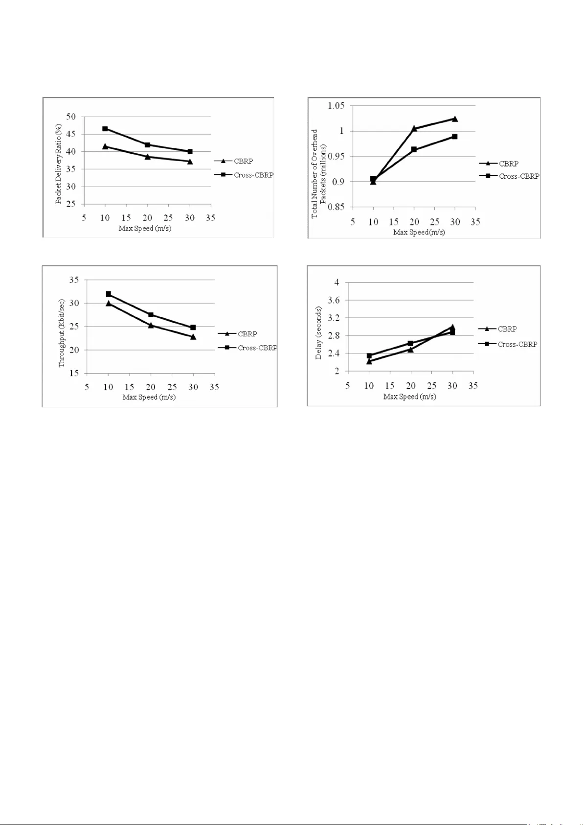
1 Improving Perform ance of Cluster Ba sed Routing Protoco l using Cross-Layer Design Seyed Kazem Jahanbakhsh Marzieh Hajhosseini Department of Electrical E ngineering Department of Electronic Eng ineering Sharif University of T echnology Central Tehran branch of Isla mic jahanbakhsh@ee.sha rif.edu Azad Universit y meli_h55@yahoo.com Abstract- The m ain goal of routing protocol is to efficiency delivers data from source to destination. All routing protocols are the sam e in this goal, but the w ay they ado pt to achieve it is differen t, so routin g strategy has an egregious role on the perform ance of an ad hoc network. Most of routing proto cols prop osed for ad hoc networks have a flat structure. These protocols expand the control overhead pack ets to discover or m aintain a route. On the other hand a num ber of hierarchica l-based routing proto cols have been developed, m ostly are based on layered design. These proto cols im prove network perform ances especially when the network size grows up since details abo ut rem ote portio n of network can be handled in an aggregate m anner. Although, there is another app roach to design a protocol called cross-la yer design. Using this app roach inform ation can exchange between different layer of proto col stack , result in optim izing network perfor mance s. In this paper, we intend to exert cross-layer design to optim ize Cluster Based Routin g Protoco l (Cross-CBRP). Using NS-2 network simulator we evaluate rate of cluster head chan ges, throughpu t and pack et deliver y ratio. Com parisons denote that Cross-CBRP has better perform ances with respect to the o riginal CBRP. Keywords: Cross-layer design, Cross-CBRP, Cluster head election I. I NTRODUCCTION When utilizing a communicatio n infrastructure is expensive or impossible, mobile users can still communicate with each othe r through a wireless ad hoc network. Because of limited radio range of mobile nodes a packet is constrained to traverse several hops. Moreover, the mobility of nodes combined with transient nature of wireless links cause network topology changing. Because of these issues a number of routing proto col with differe nt structures created; flat routing proto cols and hierarchical routing proto cols. In an ad hoc network with flat routing protocol all nodes have t he same r ole in packet for warding. Therefore protocol performances degrade when the network size increases. In hierarchical routing protocol like fewer nodes have outstandin g role in packet routing and other nodes role is incons picuous. CBRP is a routing protocol that has a hierarchical-based design [7], [9]. This proto col divides the netw ork area into several smaller areas called cluster. The clustering algorithm of CBRP is Least Cluster Change or LCC [10] means the node with the lowest ID among its neighbors elects as cluster head. Other nodes lie into radio range of this cluster head will be the ordinary nodes of that cluster. Because of mobility of nodes in ad hoc network this is probable that elected cluster head to be too mobile. In addition, because nodes w ith cluster head role consume more power than ordinary nodes, mobile node with lower ID discharge soon. Through these reasons cluster head election procedure used in CBRP is not suitable. We used cross-layer design to solve this prob lem. Although cross-layer appro ach to netw ork design can increase the design complexity, using a compilation of cross-layer and layered principles to network design in a good appro ach. In such a structure each layer is characterized by some parameters. These parameters then passed to adjac ent layers to help them adapt themselves for best suit the current channel, netw ork, and ap plications. To realization this approach, signal strength was used to determine mobility of nodes. This parameter is shared between Phy, MAC and network layers to achieve a better cluster head election algorithm. In fact we used cross-layer approach to elect an appro priate node as cluster head to reduction of cluster head changes rate and therefore superior protocol p erformances. II. R ELATED W ORKS A num ber of clustering algorithms have been prop osed in literatures that create clusters that their max imu m diameter can be two or more hops. Linked Clustered 2 Algorithm (LCA) [1], Lowest-ID (LID) [2], Maximum Connectivity (MCC) [3], Least Cluster Change (LCC) and Random Competition Clustering (RCC) [15] are the most famous traditional algorithms. Most of these algorithms have a simple random criterion to elect a cluster head mainly focuses on how to form clusters with a good geographic distribution, such as minimu m cluster overlap, etc. These kind of clustering algorithms don't meet stability of clusters; how ever, it is an important criterion especially w hen clustering used to support routing. To meet this end some other clustering algorithms was cre ated that considered cluster stability. A number of this kind of clustering algorithm s can find in [4], [5], [6], [12] and some other literatures. In [12] cluster head election parameter is node's mobility. In [4] cluster head election is based on mobility and p ower quantity of nodes. In [5],[6] a weight-based clustering algorithm is prop osed. Collection of mobility , link connectivity, power and distance of nodes are gathered to elect a cluster head. The advantage of these algorithms is their precise criterion in cluster head election and therefore more stable clusters creation. Although there are several proposed clustering algorithms in literatures, a few num bers of them was employed in routing protocols. CBRP and Cluster head Gateway Sw itch Routing (CGSR) used LCC as their cluster head election algorithm or [15] utilized RCC for this aim . In this paper w e focused on the clustering election of CBRP. We used cro ss-lay er approach to elect cluster heads for it. We replaced MOBIC [12] clustering algorithm instead of its original algorithm means LID. III. C BRP O VERVI EW T he idea of CBRP [7] is to divide the nodes of an Ad hoc network into a number of overlapping or disjoint clusters. Each cluster elects a node as cluster head. A cluster head exerts gateway nodes to comm unicate w ith other cluster head through them . In other word a gateway node has at least one cluster head or more. Other nodes in the cluster are ordinary nodes. Cluster heads record the mem bership information for the clusters in tw o neighbor tables. CBRP’s clustering algorithm creates clusters that their diameters are 2 hops. Intra-cluster routes (routes within a cluster) are discovered dynamically using the mem bership inform ation. CBRP is based on source routing, similar to DSR. This means that inter-cluster routes (routes between clusters) are found by flooding the Fig 1. Cluster structure i n CBRP netw ork with Route Requests (RREQ). The difference is that the cluster structure generally means that the number of nodes disturbed is much less. Flat routing proto cols, i.e. only one level of hierarchy, mig ht suff er from excessive overhead w hen scaled up. Readers is referred to [9] for an analysis of netw ork performance versus scalability. CBRP is fully distributed just like other proto cols and this is necessary because of the dynamic essence of Ad hoc netw ork topo logies. A. Cluster formation algorithm In CBRP, each node transmits some packets nam ed “Hello message” to announce its presence to its neighbor nodes. Upon receiving a hello message, each node updates its neighbor tables. Each node enters the network in the “undecided” state. Every node upon receiving hello message from its neighbors compares its own ID with its neighbor’s. If a node distinguishes that its own ID is the lowest ID between its neighbors, this node declares itself as cluster head. Every node that has a bi-directional link to this cluster head will be a member of this clus ter [7] . Clusters are identified by their respective cluster heads, which means that the cluster head must change as infrequently as possible. The algorithm is therefore not a strict “lowest-ID” clustering algorithm. A non-cluster head never challenges the status of an existing cluster head. Only w hen two cluster-heads move next to each other, one of them loses its role as cluster head (LCC)[10]. In Fig.1, node 1 is cluster head for the cluster containing nodes 2, 3, 4 and 5, and node 6 and 8 are cluster heads for two other clusters. B. Routing mechan ism in CBRP 3 Routing in CBRP is based on source routing and the route discovery is done by flooding the network with RREQ. The clustering appro ach however, means that few er nodes are disturbed, since only the cluster heads are flooded. If node X seeks a route to node Y, node X will send out a RREQ, with a recorded source r oute listing only itself initially. Any node forwarding this p acket will add its own ID in this RREQ. Each node forwards a RREQ only once and it never forwards it to node that already appear s in the record ed route. The source unicasts the RREQ to its cluster head. Each cluster-head unicasts the RREQ to each of its bi-directionally linked neighboring clusters, which has not already appear ed in the recorded route through the correspo nding gateway. This proced ure continues until the target is found or another node can supply the route. When the RREQ reaches the target, the target may choose to mem orize the reversed route to the source. It then copies the record ed route to a Route Reply packet and sends it back to the source [7]. In CBRP, a RREQ will always follow a route with the following pattern: Source → Cluster head → Gateway → Cluster head → Gateway → ··· → Destination IV. C ROSS L AYER A PPROACH F OR C BRP: C ROSS- C BRP Mob ile Ad hoc networks experience severe topolo gy changes in addition to comm on prob lems of other wireless netw orks. Successive join-and-leave nature of MANET nodes in hierarchical algorithms like CBRP, that is fully dependent on the cluster heads behavior, directly influences the overall network performance. Therefore , wise cluster formation as a mainstream part of these algorithms can improve network performance. In CBRP, cluster formation is performed w ith a sim ple and naive approach of the lowest ID. In such a raw selection, every node with the lowest ID between its local neighbors will be cluster head. Obviously, neither the network dynam ics nor the clusters stability has been considered. As mentioned earlier, in hierarchical cluster-based MANET, cluster heads play the main role in maintaining the cluster structure and standing against the destructive factors namely mobility. In the cross layer design approach proposed in this paper, cluster formation mechanism and cluster maintenance are considered with respect to proportional mobility of the node towards its neighbors. With this schem e, a node with the lowest mobility and movem ent in the pre-specified period of time will be named cluster head. By means of c luster head stabilization, netw ork will not suff er from cluster tum bling and local destruction in addition to overheads caused by that. Recent experimental studies have demonstrated that as the availability of links fluctuates because of channel fading phenomen a, the effects of the impairm ents of the wireless channel on higher-layer proto cols are not negligible,. Furthermore, mobility of nodes is not considered. In fact, due to node mobility and node join- and-leave events, the network may be subject to frequent topological reconfigurations. Thus, links and clusters are continuously established and broken. This process in hierarchical cluster-based architecture will result in excessive overhead and cluster head change w hich degrades performance of the whole network. For the above reasons, new analytical parameters and information from link layer are required to help network layer to determine connectivity conditions; containing mobility and fading channels. In our new approach, the sense of network dynam ics and topography changes in physical layer (in the form of received signal power) is fully exploited in netw ork layer cluster formation to achieve energy efficiency and robustness against topological dynam icity [11]. A. An aggregate lo cal mobility for Cross-CBRP We use Rayleigh fading model to describe the channel between wireless nodes in a cluster. For a transmitter- receiver separation x, the channel gain is given by: n d x d L x h ) )( ( ) ( 0 0 (1) where L ( d 0 ) = G t G r l 2 /16π 2 d 0 2 is the path loss of the close-in distance d 0 , G t is the antenna gain of the transmitter, G r is the antenna gain of the receiver, l is the wavelength of the carrier frequency , n is the path loss exponent (2 ≤ n ≤ 6), and ξ is a normalized random variable that represents the power gain of the fading. Using equation (1), will give us P r /P t x -n ξ , and by neglecting randomness of fading effect we will have, n t r x P P (2) T he equation (2) shows an inverse n-th power dependence of the radio of received and transm itted power on the physical distance between the transmitter and the receiver. In reasonably short time scales e.g. a few seconds, the surrounding environm ent is unlikely to change 4 significantly , therefore .The variable channel gain caused by the effects of multipath, small-scale and large scale fading can be ignored. In this situation the variation of the received signal power will be a good indicator for local mobility of every node. T he ratio of P r between two successive packet transmissions i.e. periodic “hello” mess ages from a neighboring node will get us a good knowledge about the relative mobility between two nodes. From this the relative mobility metric M Y rel (X) at a node Y with respect to X can be define as: ) ( log 10 ) ( . 10 old r new r rel Y Y X Y X p p X M (3) Now consid er a node with m neighbors; there will exist m such values for M Y rel (X) . This situation is depicted in Fig.2. W e use the aggregate local mobility value M Y at any node Y by calculating the variance (with respect to zero) of the entire set of relative mobility samples M Y rel (X i ) , w here X i is a neighbor of Y as proposed in [12]: ] ) [( )} ( var{ 2 1 rel Y m i i rel Y Y M E X M M (4) In this paper M Y rel (X i ) , in (3) is used as a mobility characteristic of a node with respect to its neighbors. As it can be seen from (4) every node is able to calculate M Y , just from a comparison between received powers of “hello” packets in the successive periods of time. Aggregate local mobility of nodes w ill be included in the advertising packets and broadcasted to neighbors in addition to the node ID and other CBRP’s common fields. Resorting to this new field of information, each node makes a table w hich keeps the track of tw o parameter for every neighbor; ID and aggregate local mobility. During the cluster formation algorithm, when eligible nodes are competing for taking cluster head role in a distributed manner, aggregate local mobility of every node computed formerly by advertised “hello” packets is compared with aggregate local mobility of its neighbors. For the sake of maximu m stability in this heuristic topolo gy control algorithm, the node with the lowest aggregate local mobility will win and take the cluster head role. For better adaptation to uncommon circums tances, lowest ID will be considered just in the rare condition of mobility metric equality. Here, it should be highlig hted that M Y and power estimations which are the building blocks of determinant tables in addition to the tables themselves are gathered, processed and stor ed lo cally just w ith the aid o f Fig.2 . Calculation of A ggregate Relative Mobility (a) “Hello” packet recept ion at Y from neighbor. (b) Successive Rx Pow er Measurements at Y due to X. neighbor’s “hello” packets. Despite the fact that each node computes its mobility just with respect to neighbor’s contributions independently (an indirect appro ach), there is no need to have a central node to collect and redistribute node’s inform ation w ith a lot of overhead w hich means scalability in a m obile Ad hoc network. B. Distributed Cluster Formation Algorithm for Cross- CBRP In order to use the aggregate mobility metric presented in the section ″A″ for clustering, we prop ose a tw o step distributed clustering algorithm which use the mobility metric as a basis for cluster formation. You can find the description of the algorithm in the follow ing paragraph: All nodes send (receive) “Hello” messages to (from) their neighbors. Each node measu res the received power levels of two successive transmissions from each neighbor, and then calculates the pair wise relative mobility metrics using (3). Also, every node extracts the relative mobility metric of every neighbor from received “hello” packet. Then, each node computes the aggregate relative mobility metric M Y using (4). All nodes start in Cluster-Undecided state. Every node broad casts its own mobility metric, M Y (initialized to 0 at the beginning of operation) in a “hello” message to its 1-hop neighbors, once in every Broad cast-Interval (BI) period . If this node is not already in the neighbor table of each neighboring node, w ill be stored in the neighbor table of them along with a time-out period (TP ) seconds as a new neighbor. Otherwise neighboring node situation becomes update. Fig.3 shows the distributed algorithm in details. T his algorithm is distributed. Thus, a node receives the M Y -values from its neighbors, and then compares them with its ow n. If a node has the lowest value of M Y amongst 5 A node like m receives a “hello” packet from node n : m searches its neighbor table if n is already in the neighbor table determine the signal power of the “hello” packet received from node n . calculate relative mobility metric usin g (2). update neighbor table’s fields of node m for n. update number of cluster head related to m . if m is a cluster head in the proximity of other cluster head if aggregate relative mobility of m is less than node n m remains as cluster head. node n give up cluster head role and becomes a mem ber o f m. return. else if aggregate local mobility of m is equal to the n if m has a lower ID m remain as the cluster head. n becomes a member of m . return. else m is a mem ber of its neighbor cluster head return. else m is a member of its neighbor cluster head return. else if m is a member and it has no cluster head now for every neighbors of m if aggregate local mobility of m is less than the related neighbor’s m is cluster head. m determines its aggregated relative mobility usi ng (3) m broadcasts a “hello” packet to intro duce itself to its neighbors. else m status will change to undecided state. a new cluster must be generated. return. end for else record this new neighbor in the neighbor table and wait for the next receiving sig nal of n. wait for the next event. Fig. 3. Distributed Clus ter Formation Al gorithm for Cross-CBRP all its neighbors, it assum es the status of a cluster head. Then this node broad casts a “hello” packet to introduce itself as cluster head. In case where the mobility metric of two cluster head nodes is the same, and they are in competition to retain the cluster head status, then the selection of the cluster head is based on the Lowest ID algorithm in which the node with lowest ID gets the status of the cluster head. If a node with cluster mem ber status and w ith low mobility moves into the range of another cluster head node w ith higher mobility, re-clustering will not triggered (similar to LCC [10]) because this is in contrary to the netw ork stability and overhead mitigation. TABLE 1. S IMULATION P A RAMETERS VI. R ESULT & D IS CUTION The simulations were performed using the ns-2 network simulator with the MANET extensions [13]. The mobility scenarios were rando mly generated using the rando m waypoint mobility model with input parameters such as maximum speed, number o f nodes, area size, etc. Traffic is generated using NS-2 CBR traffic generator. There are simultaneously 60 CBR traffic flows associated with randomly selected disjoint source and destinatio n nodes. Packet size is set to 512 bytes. We used DropTail/PreQueue for implementing the interface queue. This type of queue inserts the routing protocol packets at the head of the queue and all other packets at the back. Size of the queue buffer sets to 50. We implemented Cross-CBRP by doing the required modification on the latest implementation of CBRP in ns-2 environment [14]. The simulation parameters have been listed in Tab le 1. Two kinds of scenarios were used to evaluate the network performances. Each simulatio n has been run for 300 seconds, and the results are averaged over 5 randomly generated nodal spatial topolo gies. We precisel y compared performance para meters of ou r proposed ap proach with the original CBRP such as rate of cluster head changes, throughput, packet delivery ratio , delay and over head. Fig. 4. Number of Cluster Head Changes vs. Speed Parameter Meaning Value N Numbe r o f No des 100 m × n Size of the scenario 1000 x 1000 (m 2 ) Max Speed Maximum Speed 10,20,30 (m/s) Tx Transmission Range 250 m P.T Pause Time 0 sec 6 a). Packet Delive ry Ratio vs. Speed b). Throughput vs. Spee d c). Number of Over head Packets vs. Speed d). Average End-to-e nd Delay vs. Speed Fig .5. Performance Com parison between CBRP and Cross-CBRP Throughput is defined as the average number of data packets received at destinations during si mulation time and packet delivery ratio is defined as the total number of data packets sent by traffic sources to the total number of data packets received at destinatio ns, overhead is defined as the total number of control p ackets includi ng hello packets and finally end-to-end delay is defined as the average time elapsed that a pac ket originated at the source node, receives at the destination nod e. In the first scenario, the rate of packet sent is 4 byte per seconds. Max mobility speed has been considered 10, 20 and 30 m/s ec. Fig.4 show s the effect of varying mobility on the performance of Cross-CBRP w ith respect to CBRP. It can be seen explicitly from Fig.4 that Cross-CBRP outperforms CBRP by averagely 37% improvement for cluster head changes. It is very clear that Cross-CBRP yields a remarkable gain over CBRP because of its capability of adapting itself to the mobility of nodes. From cluster head changes vs. mobility curve, w e can conclude that Cross-CBRP is suitable for stable cluster formation in situations involvin g mobility. Fig.5 (a) demonstrates the packet delivery ratio differences of two algorithms in the existence of mobility . Again w e can see that in average the Cross-CBRP performs about 9% better than CBRP because of the cross-layer adaptation technique that has been used in its design. The throughput plays an important role in comparing different network protocols from QoS perspective. Fig.5 (b) demonstrates the results of measured throughput for tw o previously discussed protocols. The performance results show more efficient behavior of Cross-CBRP in comparison with CBRP with respect to mobility . As it is apparent from the Fig.5 (b), the Cross-CBRP outperforms CBRP about 8.5% which again supports this claim that increasing cluster stability we will give us better netw ork performance. The total number of control packets as the proto col overhead of these two proto cols is compared with each other in (c) .As depicted from this figure it can be seen that Cross-CBRP perfor ms better than CBRP according to this fact that it decrea ses the cluster re formations. Finally in Fig.5 (d) the end-to-end delay of two protocols analyzed which de monstrates an ignorable difference 7 0 10 0 20 0 30 0 40 0 50 0 60 0 70 0 80 0 90 0 0 2 4 6 8 P a c k et R a t e ( p k t / s e c ) Nu mb er o f C l u s t erh ea d C h a n g es CB RP Cro ss -CBRP Fig.6. Number of Cluste r Head Changes vs. packet Rate between them. In the second scenario we changed the sent packet rate from 1 pkt/sec to 8 pkts/sec. In this scenario we intend to study effect of varying traffic on the perfor mance of Cross- CBRP with respect to origina l-CBRP. As shown in Fig.6 cluster head change rate increases when the pac ket rate is augmented. When injected traffic to network increases some reaso ns can cause packets do not received by do wn stream node - for example lack of route or impossibility to access to the media – so packets will hold in interface queue. If this buffer overflows the last inco ming packet will discard. Therefore , if there are some hello packet in this queue t hese hello packets reach to the neighbors nodes by delay. T w o cluster head may ha ve a uni-directional link with each other in this elapsed time; so both of them remain as cluster head until their link changes to bi- directional link. When hello messages reach to destination uni-directional link can change to bi-directio nal. Therefore, one of adjac ent cluster heads must change its role. This w ill cause the cluster head changing rate increase by increasing injected traffic to network. As we seen in this figure the rate of cluster head changes in Cross-CBRP is out perform original CBRP about 30% in low pac ket rate and 10% in a high packet rate. This is again because of Cross-CBRP capability to adapting itself to the network co nditions. Fig.7 show s the packet delivery ratio versus packet rate. Injecting traffic to the netw ork causes degrading probability of access to the media. Whatever, the injected packet to network increases, packet delivery ratio decreases. Again we can see that in average the Cross- CBRP performs about 9% better than CBRP because of the cross-layer adaptation technique that has been used in its design. The last graph is related to network throughput. 20 30 40 50 60 70 80 90 10 0 0 2 4 6 8 P a c k et R a t e( p k t / s ec ) P . D . R (% ) C B R P C r os s-C B R P Fig.7. Packet Delive ry Ratio vs. Packet Rate Fig.8 show s the results of measu red throughput for tw o previously discussed proto cols. Althoug h packet delivery ratio decreases w hen traffic rate increases, increasing throughput continued. This is because of increasing amount of injected traffic in the network that cause number of received packet bytes increases. Again it can be seen from Fig.8 that Cross-CBRP throughput outperforms original-CBRP about 10% when traffic increases. VII. C ONCL USION & F UTURE W ORKS Clustering algorith ms as discussed in section IV provide more efficie nt way to utilize the network resources like bandwidth and energ y. Mob ility of nodes in MANET has a destructive role in the efficie nt resource allocation. In this paper, w e presented a new app roach to cross-layer design of CBRP to enhance its eff iciency with respect to the existence of mobility in Ad hoc networks. Cross-CBRP, by considering multiple layers such as ph ysical, MAC and network layer tries to provide an adaptive clusterin g algorithm. Using ns-2 we demonstrated that Cross-CBRP outperforms CBRP in different perfor mance factors. Therefore, we conclude that Cross-CBRP, using mobility 15 17 19 21 23 25 27 29 31 33 35 0 2 4 6 8 P a c k et R a t e (p k t / s ec ) T h ro u g h p u t(K b it/ s ec ) C B R P C r os s- C B R P Fig.8. Throughput vs. Packet Rate 8 parameter sensed via physical layer, is able to behave much better than CBRP which does not account for mobility issues at all. We believe that the cross-layer approach for designing clustering proto col for Ad hoc and wireless sensor networks is a productive field of research. It is possible, to account for other parameters from the physical layer such as channel state to provide more reliable adaptive clustering proto cols regarding varying behavior of wireless channels like fading and noise eff ects. R EFERENCES : [ 1] D. J. Bak er and A. Ephremides. The architectural organization of a mobile radio network via a distributed algorithm. IEEE Transaction s on Communicati ons , 29(11):1694 -1701, 19 81. [2] A. Ephremides, J. Wie selthier, and D. Baker . A design concept for reliable mobile radio ne twork with frequency hopping signaling. In Proceedings of IEEE 75 , pages 56-73, 1987. [3] A. K. Parekh. Selecting r outers in ad hoc w ireless networks. In ITS , 1994. [4] I. I. ER and W. K. G. Seah, “Mobility Based d-Hop Clustering Algorithm for Mobile Ad hoc Networks,” Proc. IEEE Wireless Communications and Networking Conference. March 2004. [5] R. Purtoosi, H. Taheri, A. Mohammadi and F. Froozan, “A light- weight Contention-Based Clustering Algorithm for Wireless Ad hoc Networks,” Proc. Forth International Conference on Computer and Information Technology, IEEE Sept 2004. [6] M. Chatterjee, Sajal. K. Das, and D. Turgut, “An on- demand weighted clustering algorithm (WCA) for Ad hoc networks,” Global Telecommunications Conference, 2000. GLOBECOM apos ; 00. IEEE Volume , Issue , 2000 Page(s):1697 - 1701 vol.3 [7] M. Jiang, J. Li, and Y.C. Tay , “Cluster Based Routing Protocol,” IETF Draft , August 1999. [8] E. setton, T. Yoo, X. Zhu, A. Goldsmith and B. Girod, “cross layer design of ad hoc network for real time video streaming ”, IEEE wireless communications, August 2005, pp. 59-65. [9] J. Mingliang, Y.C. Tay and P. Long, "CBRP: A Cluster- based Routing Pro tocol for Mobile Ad hoc Networks", National University of Singapore, http://www.comp.nus.edu.sg/~tayyc/cbrp/hon.ppt . [10] C. C. Chiang, H. K. Wu, W. Liu, and M. Gerla, “Routing in clustered multi-hop mobile wireless networks with fading channel,” Proceedings of IEEE Singapore International Conference on Networks ( SICON ’ 97 ), 1997, pp. 197-211 . [11] T. Melodia, M. C. Vuran, and D. Pompili, "The State of the Art in Cross-Layer Design for Wireless Sensor Networks", Springer Lecture Notes in Computer Science (LNCS), vol. 3883, June 2006. [12] P. Basu, N. Khan, and T.D.C. Little, “A Mobil ity Based Metric for Clustering in Mobile Ad hoc Networks,” Proc. IEEE ICDCSW 21st International Conference on Distributed Computing Systems Workshops , April 2001 . [13] Wireless and Mobility Extension s to the ns-2 Network Simulator, CMU Monarch Project. http://monarch.cs.cmu.edu/cmu-ns.html [14] Network Simulator - ns-2. UC Berkeley. http:/ /ww w- mash.cs.berkeley .edu/n s/ [15] K. Xu, X. Hong and M. Gerla, "La ndmark Routin g in Ad Hoc Networks with Mobile Backbones" Computer Science Department University of California, Los Angeles.
Original Paper
Loading high-quality paper...
Comments & Academic Discussion
Loading comments...
Leave a Comment