Joint Source-Channel Codes for MIMO Block Fading Channels
We consider transmission of a continuous amplitude source over an L-block Rayleigh fading $M_t \times M_r$ MIMO channel when the channel state information is only available at the receiver. Since the channel is not ergodic, Shannon's source-channel s…
Authors: Deniz Gunduz, Elza Erkip
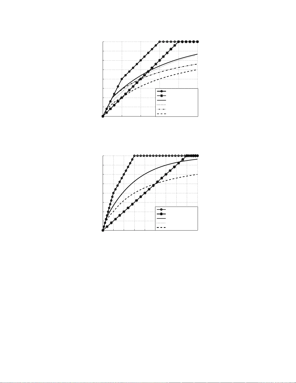
1 Joint Source-Channel Codes for MIMO Block F ading Channels Deniz G ¨ und ¨ uz, Elza Erkip Abstract W e consider transmission of a continuous amplitude source over an L -block Rayleigh fading M t × M r MIMO channel when the ch annel state information is on ly av ailable at the recei ver . Since the ch annel is not ergo dic, Shannon’ s source-chann el separation theo rem bec omes obso lete and the optimal performance r equires a joint source -channel approach. Our goal is to minimize the expected end-to-end distortion, particularly in the high S NR regime. T he figure of merit is the distortion exponent, defined as the expon ential decay rate of the expected distortion with increasing SNR. W e provide an upper bound and lower bounds for t he distortion expon ent with respect to the band width ratio among the channel and source bandwidths. For the l o wer bounds, we analyze three differen t strategies based on layered source coding concatenated with progressi ve, superposition or hybrid digital/analog t ransmission. In each case, by adjusting the system parameters we optimize the distortion exponen t as a function of the bandwidth r atio. W e prove that the distortion exp onent upper bound can be achie ved when t he channel has only one degree of freedom, that is L = 1 , and min { M t , M r } = 1 . When we have more degrees of freedom, our achie v able distortion expon ents meet the upper bound for only certain ranges of the bandwidth ratio. W e demonstrate that our results, which were deri ved for a complex Gaussian source, can be extended to more general source distribu tions as well. Index T e rms Broadcast codes, distortion exponent, div ersity-multiplexing gain tradeoff, hybrid digital/analog coding, joint source-chann el coding, multiple input- multiple output (MIMO), successiv e refinement. I . I N T R O D U C T I O N Recent a dvances in mob ile c omputing a nd hardware tech nology en able transmiss ion o f rich mu ltimedia contents over wireless networks. Examples inc lude digital TV , voice a nd video transmission over cellular and wireless LAN n etworks, and se nsor networks. W ith the high d emand for such se rvices, it be comes The material in this paper was presented in part at the 39th As ilomar Conferenc e on Signals, Systems, and Computers, Pacific Grove , CA, Nov . 2005, at the IEEE Information T heory W orkshop, Punta del Este, Uruguay , March 2006, and at the IEEE Internation al Symposium on Information Theory (ISIT), Seattle, W A, July 2006. This work is partiall y supported by NSF grants No. 0430885 and No. 0635177. Deniz G ¨ und ¨ uz was with Depart ment of Electrica l and Compute r Engineering, Polytech nic Uni ve rsity . He is now with the Department of Electric al E ngineeri ng, Princet on Unive rsity , Princeton, NJ, 08544, an d also with the Depa rtment of Electric al Engineeri ng, Stanford Uni versity , Stanford, CA, 94 305. Elza Erkip is wi th the Depart ment of Ele ctrical and Computer Enginee ring, Polytechnic Uni versity , Brooklyn, NY , 11201. Email: dgunduz@prince ton.edu, elza @poly .edu. 2 crucial to i dentify the system limitations, define the appropriate performanc e metrics, and to design wireless systems that a re capable of ac hieving the best performance by overcoming the cha llenges po sed by the syste m requirements and the wireless en vironment. In general, mu ltimedia wireless communica- tion requires transmitting an alog so urces over fading c hanne ls while satisfying the end -to-end average distortion and delay requirements of the application within the power limit ations of the mo bile terminal. Multiple antenna s at the transceivers have been proposed as a viable tool that can remarkably improv e the pe rformance o f mu ltimedia trans mission over wireless channe ls. The a dditional degrees of freedom provided by multiple input multiple output (MIMO) s ystem can be utilized in the form of spatial multiplexing gain and/or spatial diversity g ain, that is, either to transmit more information or to increa se the reliability of the transmission. The tradeof f between these two ga ins is exp licitly c haracterized as the div ersity-multiplexing g ain tradeoff (DMT) in [1]. How to translate this tradeoff into an improved overall system performance depend s on the applica tion req uirements and limitations. In this pa per , we c onsider transmission of a c ontinuous amplitude sou rce over a MIMO block Ray leigh fading channe l. W e are interested in minimizing the end-to-end average d istortion of the sou rce. W e assume that the instantane ous channel state information is only av ailable at the rec eiv er (CSIR) . W e consider the ca se where K so urce samples are to be transmitted over L fading blocks sp anning N channe l use s. W e define the bandwidth ratio o f the system as b = N K channe l use s pe r source sample , (1) and analyze the s ystem performance with respect to b . W e assu me that K is large e nough to ach iev e the rate-distortion performance o f the underlying source, and N is lar ge enoug h to design codes that can achieve all rates below the instantane ous ca pacity of the block fading channel. W e are particularly interested in the high S N R behavior of the expected distortion (ED) which is characterized by the distortion exponent [2]: ∆ = − lim S N R →∞ log E D log S N R . (2) Shannon ’ s f undame ntal source-chan nel separation theorem does not apply t o our s cenario as the channel is no more ergodic. Thus, the optimal strategy requires a joint so urce-chan nel co ding approach . The minimum expected en d-to-end distortion depe nds on the source characteristics, the distortion metric, the power c onstraint of the transmitter , the joint co mpression, ch annel coding and transmiss ion techniques used. Since we are interested in the average distortion of the s ystem, this requires a strategy that performs ‘well’ over a r ange of chann el conditions. Our approach is to first compress the source i nto multiple layers, where each layer succe ssively refines the previous laye rs, an d then transmit these layers at varying rates, 3 hence providing u nequa l e rror protection so that the recon structed signal q uality ca n be adjusted to the instantaneou s fading s tate without the avail ability of the cha nnel state information a t the transmitter (CSIT). W e co nsider transmitting the source layers either progres siv ely in time, layered sou r ce coding with pr ogr essive transmiss ion (LS), or simultaneo usly by superpos ition, b r o adcas t strate gy with lay ered source (BS). W e also discus s a hy brid d igital-analog extension of LS called hybrid-LS (HLS). The ch aracterization of distortion expo nent for fading channe ls has rec ently be en in vestigated in several papers. Distortion exponen t is first d efined in [2], and simple transmission sc hemes over two pa rallel fading c hanne ls are compa red in terms o f distortion expo nent. Our prior work includes maximizing distortion exponent using layered sou rce transmiss ion for co operativ e relay [3], [4], [5], for SISO [6], for MIMO [7], a nd for parallel ch annels [8]. Holliday and Goldsmith [9] analyze high SNR be havior of the expected distortion for sing le laye r trans mission over MIMO without explicitly giving the achieved distortion exp onent. Hyb rid d igital-analog transmission, fi rst p roposed in [10] for the Gaussia n broadca st channe l, is con sidered in terms o f distortion exponent for MIMO c hanne l in [11]. Others have foc used on minimizing the end -to-end source distortion for gen eral SNR values [15 ], [16]. Recently , the LS and BS s trategies introduc ed here have been analyz ed for finite SNR and finite numbe r of source layers in [17]-[22]. This pap er deriv es explicit expressions for the a chiev able distortion exponen t of LS, HLS an d BS strategies, and compares the achiev able exponents with an uppe r bound deriv ed by as suming perfect channe l state information at the transmitter . Our resu lts re veal the following: • LS strategy , wh ich can ea sily be implemented by c oncatena ting a laye red s ource coder with a MIMO chann el encoder that time-shares among different code rates, improves the distortion exponen t compared to the s ingle-layer a pproach of [9] ev en with limited numbe r of s ource laye rs. Howe ver , the distortion exponent of LS still falls sh ort of the upper bound. • While the hyb rid d igital-analog sche me mee ts the distortion expone nt uppe r b ound for sma ll band- width ratios as shown in [ 11], the improv ement of h ybrid extens ion o f LS (HLS) over p ure progressi ve layered digital transmission (LS) becomes i nsignifica nt as the ban dwidth rati o or the number of digital layers increases . • T ransmitting layers s imultaneously as s ugges ted by BS provides the optimal dis tortion exponen t for all band width ratios when the s ystem has on e degree of freedom, i.e., for single block MISO/SIMO systems, a nd for high bandwidth ratios for the gene ral MIMO system. H ence, for the mentioned cases the problem of charac terizing the distortion expo nent is solved. • There is a close relationship between the DMT of the underlying MIMO c hanne l and the ac hiev able distortion exponent of the proposed sc hemes. For L S a nd HLS, we are able to give an explicit 4 characterization o f the achiev able distortion exponent once the DMT of the system is provided. For BS, we enforce succ essive d ecoding at the receiv er and the a chiev able d istortion exponent closely relates to the ‘ succes sive decod ing diversity-multiplexing tradeof f ’ which will be rigorously defin ed in Section V. • The corresp ondenc e betwee n s ource trans mission to a sing le user with unkn own noise variance and multicasting to users with dif ferent noise levels [10] sugge sts that, our a nalysis would a lso apply to the multicas ting case whe re ea ch receiver has the sa me nu mber of anten nas an d ob serves an inde penden t block fading Ra yleigh chan nel possibly with a dif ferent me an. Here the goal is to minimize the expected dis tortion of each user . Alternati vely , each user may have a s tatic channe l, but the ch annel ga ins over the us ers ma y b e rand omly distributed with independ ent Rayleigh d istrib ution, where the objective is to minimize the source distortion averaged over the users. • While minimizing the end-to-end d istortion for finite SNR is still an open problem, in the high SNR regime we are able to provide a complete s olution in certain sce narios. Using this high SNR analysis, it is a lso p ossible to ge neralize the results to non -Gaussian s ource distributi ons. Furthermore, LS and BS strategies moti vate s ource and chan nel c oding strategies that are shown to pe rform very well for finite SNRs as well [17]-[22]. W e use the following n otation throug hout the p aper . E [ · ] is the expectation, f ( x ) . = g ( x ) is the exponential equ ality de fined a s lim x →∞ log f ( x ) log g ( x ) = 1 , while ˙ ≥ and ˙ ≤ are defined similarly . V ec tors and matrices are denote d with bold ch aracters, where ma trices a re in c apital letters. [ · ] T and [ · ] † are the transpose and the conjuga te transpose operations, respec ti vely . tr ( A ) is the the trace of matrix A . For two Hermitian matrices A B means that A − B is p ositi ve-semidefinite. ( x ) + is x if x ≥ 0 , a nd 0 otherwise. W e deno te the s et { [ x 1 , . . . , x n ] : x i ∈ R + , ∀ i } by R n + . I I . S Y S T E M M O D E L W e conside r a discrete time continuou s amplitude (analog) source { s k } ∞ k =1 , s k ∈ R available at the transmitter . For the an alysis, we focus on a memoryless, i.i.d., complex Ga ussian s ource with indep enden t real and imaginary c omponen ts each with variance 1 /2. W e use the distortion-rate func tion of the c omplex Gaussian source D ( R ) = 2 − R where R is the source coding rate in bits pe r source sample, a nd conside r compression strategies tha t me et the distortion-rate bound. Althoug h in Sections III-VI we use properties of this complex Gaus sian source (suc h as its d istortion-rate function and s ucces siv e refina bility), in Se ction VIII we prove that ou r results c an be extended to any complex source with finite sec ond moment and finite dif ferential en tropy , with squared-error distortion metric. As s tated in S ection I, we as sume that K source samples are transmitted in N channel uses which corresponds to a bandwidth ratio o f b = N/K . 5 In all our deriv a tions we allo w for an arbitrary bandwidth ratio b > 0 . W e assu me a MIMO bloc k fading channel with M t transmit and M r receiv e antenn as. The channe l model is y [ i ] = r S N R M t H [ i ] x [ i ] + z [ i ] , i = 1 , . . . , N (3) where q S N R M t x [ i ] is the trans mitted s ignal a t time i , Z = [ z 1 , . . . , z N ] ∈ C M r × N is the complex Gaus sian noise with i.i.d entries C N (0 , 1) , and H [ i ] ∈ C M r × M t is the c hannel matrix at time i , which has i.i.d. entries with C N (0 , 1) . W e have a n L -bloc k fading channel, that is, the ch annel obse rves L different i.i.d. fading rea lizations H 1 , . . . , H L each lasting for N/L c hannel uses. Thus we have H k N L + 1 = H k N L + 2 = . . . = H ( k + 1) N L = H k +1 , (4) for k = 0 , . . . , L − 1 as suming N /L is integer . The rea lization of the chan nel matrix H i is as sumed to b e known by the receiv er an d unknown by the transmitter , while the trans mitter k nows the statistics of H i . The codeword, X = x [1] , . . . , x L ∈ C M t × N is normalized so that it satisfies tr ( E [ X † X ]) ≤ M t N . W e assume Gau ssian code books which can a chieve the instantaneous capa city of the MIMO channel. W e define M ∗ = m in { M t , M r } and M ∗ = m ax { M t , M r } . The sou rce is transmitted through the c hanne l using one of the joint s ource-cha nnel coding schemes dis- cusse d in this paper . In general, the sou rce encode r matches the K -length source vector s K = [ s 1 , . . . , s K ] to the ch annel input X . The deco der map s the rece i ved s ignal Y = y [1] , . . . , y [ N ] ∈ C M r × N to an estimate ˆ s ∈ C K of the source . A verage distortion E D ( S N R ) is defined as the average mean squared error between s and ˆ s at average chan nel signal-to-noise ratio S N R , where the expectation is taken with respect to all source s amples, chann el realizations and the c hanne l noise. The exact expression of E D ( S N R ) for the strategies introduced will be provided in the resp ectiv e sec tions. As men tioned in S ection I, we are interes ted in the high SNR be havior o f the expected d istortion. W e optimize the system performance to max imize the distortion exponent defi ned in Eqn. (2). A distortion exponent of ∆ mea ns that the expe cted distortion dec ays as S N R − ∆ with increasing SNR when S N R is high. In order to obtain the e nd-to-end distortion for our propose d s trategies, we will nee d to charac terize the error rate of the MIMO cha nnel. Since we a re interested in the high SNR regime, we use the outage probability , wh ich ha s the s ame exponential behavior as the chan nel error probab ility [1]. For a family of codes with rate R = r log S N R , r is define d as the mu ltiplexing gain of the family , and d ( r ) = − lim S N R →∞ log P out ( S N R ) log S N R (5) as the diversity ad vantage, where P out ( S N R ) is the ou tage probability of the cod e. The diversit y gain d ∗ ( r ) is define d as the supremum of the div ersity a dvantage over a ll possible c ode families with 6 multiplexing g ain r . In [1], it is shown that there is a fundame ntal trade off between multiplexing and div ersity gains, also known as the d i versity-multiplexi ng ga in tradeo f f (DMT), and this tradeo f f is explicitly cha racterized with the follo wing theorem. Theorem 2.1: (Corollary 8 , [1]) For a n M t × M r MIMO L -block f ading c hannel, the optimal tradeoff curve d ∗ ( r ) is given b y the piecewise-linear func tion connecting the points ( k , d ∗ ( k )) , k = 0 , 1 , . . . , M ∗ , where d ∗ ( k ) = L ( M t − k )( M r − k ) . (6) I I I . D I S T O RT I O N E X P O N E N T U P P E R B O U N D Before we study the performance of various source-cha nnel cod ing strategies, we ca lculate an uppe r bound for the d istortion exponent of the MIMO L -bloc k fading ch annel, ass uming tha t the transmitter has access to perfect c hannel state information at the b eginning of each block. Then the source-chan nel separation the orem ap plies for each bloc k an d trans mission at the h ighest rate is p ossible with zero ou tage probability . Theorem 3.1: For transmiss ion o f a memoryles s i.i.d. comp lex Ga ussian source over an L -block M t × M r MIMO chann el, the distortion expone nt is upp er bou nded by ∆ U B = L M ∗ X i =1 min b L , 2 i − 1 + | M t − M r | . (7) Pr oof: Proof of the theorem can be found in Appen dix I. Note that, increasing the n umber of antenna s at either the transmitter o r the rec eiv er by one does not provide an increas e in the dis tortion exponent upper bound for b < L (1 + | M t − M r | ) , since the performance in this region is bo unded by the ban dwidth ratio. Add ing o ne a ntenna to bo th side s inc reases the uppe r boun d for all bandw idth ratios, while the increas e is more pronoun ced for high er bandwidth ratios. The distortion exponent is b ounded by the highest di versity g ain LM t M r . In the case of M × 1 MISO sys tem, and alternativ ely 1 × M SIMO s ystem, the u pper boun d can be simplified to ∆ U B M I S O /S I M O = m in { b , LM } . (8) W e next discuss how a simple transmis sion strategy cons isting of sing le layer d igital transmission per- forms with respe ct to the u pper b ound. In single layer digital transmission, the sou rce is first c ompresse d at a specific rate b R , the c ompresse d b its are ch annel coded at rate R , a nd then trans mitted over the channe l. This is the approac h taken in [2] for two-parallel channels, in [3] for cooperative relay cha nnels, and in [9] for the MIMO chann el to transmit an a nalog source over a fading ch annel. Even though 7 y = br ∆ = d ∗ ( r ∗ ) r ∗ r d ∗ ( r ) Multiplexing gain Div ersity gain MIMO DMT curve Fig. 1. A geometric interpret ation illustra ting the optimal multiple xing gain for a single layer source-channe l coding s ystem. The intersect ion point of the DMT curve and the line y=br gi ves the optimal multiplex ing gain- distortion exponent pair . compression and channel coding are d one separately , the rate is a co mmon p arameter that can be c hosen to minimize the end-to-end distortion. No te that the transmitter choses this rate R without any channe l state information. The expected distortion of sing le layer transmission can be written as E D ( R, S N R ) = (1 − P out ( R, S N R )) D ( b R ) + P out ( R, S N R ) , (9) where P out ( R, S N R ) is the ou tage proba bility at rate R for given S N R , a nd D ( R ) is the distortion-rate function of the source. Here we assume that, in case of an ou tage, the decoder simply outputs the mean of the source lead ing to the highes t possible distortion of 1 due to the unit variance assumption. At fixed SNR, there is a trade off betwee n reliable trans mission over the ch annel (through the outage probab ility), and increas ed fid elity in sou rce reconstruction (through the distortion-rate function). T his sugges ts that there is an optimal transmission rate that achieves the optimal average d istortion. For any g i ven S NR this optimal R can be found us ing the exac t express ions for P out ( R, S N R ) a nd D ( R ) . In order to study the distortion exp onent, we conc entrate on the high SNR ap proximation of Eqn. (9). T o achieve a vanishing expected distortion in the h igh SNR regime w e nee d to incre ase R with SNR. Scaling R faster than O (log S N R ) would resu lt in an outag e probability of 1 , sinc e the instantaneous channe l capacity of the MIMO system sc ales as M ∗ log S N R . Thus we a ssign R = r log S N R , where 0 ≤ r ≤ M ∗ . Then the high SNR approximation of Eqn. (9) is E D . = D ( b R ) + P out ( R ) , . = S N R − b r + S N R − d ∗ ( r ) . (10) 8 0 1 2 3 4 5 0 0.5 1 1.5 2 2.5 3 3.5 4 Bandwidth ratio (b) Distortion exponent ( ∆ ) Upper bound(2 x 2 MIMO) Upper bound(4 x 1 MISO) Single rate (2 x 2 MIMO) Single rate (4 x 1 MISO) Fig. 2. Upper bound and single layer achie v able distortion exponents for 2 × 2 and 4 × 1 MIMO systems. Of the two terms, the one with the h ighest SNR exponen t would be do minant in the high SNR regime. Maximum d istortion expone nt is ac hiev ed when both terms have the sa me SNR expo nent. Then the optimal multiplexing gain r ∗ satisfies ∆ , br ∗ = d ∗ ( r ∗ ) , (11) where ∆ is the correspond ing distortion exponent. Eqn. (11 ) sugges ts an o ptimal o perating p oint on the DMT curve to max imize the distortion exponent o f the single layer scheme. Figure 1 sh ows a geometric illustrati on of the optimal multiplexing g ain and the correspond ing distortion exponent. A similar ap proach was taken in [9] for s ingle layer transmission with the restriction of integer multiplexing gains, and later extended to all multiplexing gains in [11 ]. Howe ver , as we argue next, ev en when all multiplexing gains are considered, this single layer approach is far from exploiting all the resources provided by the s ystem. In Figure 2, we illustrate the d istortion expo nent upper bound and the d istortion expo nent of the single layer scheme for 4 × 1 MISO and 2 × 2 MIMO systems. W e observe a significant gap be tween the uppe r bounds and the single laye r distortion exponents in b oth cases for all ban dwidth ratios. This g ap gets lar ger with increa sing degrees of freedom and increa sing b andwidth ratio. The ma jor d rawback of the sing le layer digital scheme is that it suffers from the thres hold e f fect, i.e., error probability is bounded away from z ero or an outage occurs when the chann el quality is worse than a certain thresh old, which is determined by the attempted rate. Fu rthermore, single laye r digital transmission ca nnot utilize the increase in the ch annel quality b eyond this thresh old. La ck of CSIT 9 makes on ly a statistical optimization of the compres sion/transmission rate pos sible. T o make the s ystem less sensitive to the variations in the cha nnel qua lity , we will co ncentrate on layered so urce co ding where the channel co dewords correspon ding to different layers are assigne d dif ferent rates . Using the succe ssive refin ability of the source, we trans mit more important co mpressed bits with higher reliability . The additional refinement bits are receiv ed whe n the channel quality is h igh. This provides a daptation to the cha nnel quality without the transmitter actually knowing the ins tantaneou s fading levels. W e a r gue that, due to the exponential decay of the distortion-rate function in general, layering increa ses the overall system pe rformance from the distortion exponen t perspectiv e. Our analys is in the following s ections proves this claim. I V . L A Y E R E D S O U R C E C O D I N G W I T H P R O G R E S S I V E T R A N S M I S S I O N A N D H Y B R I D D I G I TA L - A N A L O G E X T E N S I O N The first source-cha nnel cod ing scheme we conside r is bas ed on compression of the source in layers, where e ach layer is a refine ment o f the previous one s, and transmission of these layers s ucce ssiv ely in time using c hanne l code s of diff erent rates. W e call this scheme layered sour ce coding with pr ogr e ssive transmission (LS). This clas sical idea, mostly referred as progressive coding, has bee n used to various extents in the image and video standards such as JPEG2000 an d MPEG-4. After an alyzing the d istortion exponent of LS in Section IV -A, in Se ction IV -B we cons ider a h ybrid digital-analog extension called hybrid LS (HLS) where the error signal is transmitted without coding. In this sec tion we a nalyze single block fading, i.e., L = 1 , for clarity of pres entation. Gen eralization to the multiple b lock c ase ( L > 1) will be a straightforward extension of the techniques presen ted here and will be briefly discus sed in Section VI. A. Layered Sou r ce Coding with P r ogr essive T ransmission (LS) W e assume that the s ource en coder ha s n layers with each layer transmitted over the channe l at rate R i bits per chan nel us e in t i N ch annel uses for i = 1 , 2 , . . . , n , with P n i =1 t i = 1 . This is illustrated in Fig. 3(a). W e assume that t i N is large e nough to app roach the instantaneou s channel capa city . For ea ch layer this corresponds to a source coding rate o f bt i R i bits per sample, where b is the b andwidth ratio defined in (1). The i th layer is co mposed of the succes siv e refi nement bits for the previous i − 1 layers. The transmission power is kept con stant for each layer , so the optimization variables a re the rate vector R = [ R 1 , . . . , R n ] and the chan nel alloca tion vector t = [ t 1 , . . . , t n ] . Let P i out denote the outag e prob ability of layer i , i.e., P i out = P r { C ( H ) < R i } . Us ing successive refinability of the complex Gau ssian source [23], the distortion a chieved when the first i layers are 10 R 1 R 2 R n N channel uses t 1 N t 2 N t n N (a) LS strategy with n la y ers. R 1 R 2 R n t 1 ( N − K M ∗ ) t 2 ( N − K M ∗ ) t n ( N − K M ∗ ) Analog transmission K/ M ∗ (b) HLS strategy with n la y ers for b > 1 / M ∗ . R 1 , S N R 1 R n , S N R n (c) BS strategy with n la y ers. Lay ers are transmitted sim ultaneously with total p o wer allocated among them. Fig. 3. Channel and power allocation for diffe rent transmission strate gies explored in the paper . succe ssfully deco ded is D LS i = D b i X k =1 t k R k ! , = 2 − b P i k =1 t k R k , (12) with D LS 0 = 1 . Note that due to succe ssive refi nement s ource c oding, a laye r is useles s unless all the preceding layers are received succes sfully . This imposes a non-decrea sing rate alloca tion among the layers, i.e., R i ≤ R j for any j > i . Th en the expec ted dis tortion (ED) for such a rate allocation can be written as E D ( R , t , S N R ) = n X i =0 D LS i · P i +1 out − P i out , (13) where we define P 0 out = 0 an d P n +1 out = 1 . The minimization problem to be solved is min R , t E D ( R , t , S N R ) s.t. P n i =1 t i = 1 , t i ≥ 0 , for i = 1 , . . . , n 0 ≤ R 1 ≤ R 2 ≤ · · · ≤ R n . (14) 11 This is a non-linear op timization problem which can be untractab le for a gi ven SNR. An algorithm solving the above optimization problem for finite SNR is proposed in [17]. Howe ver when we focu s on the high SNR regime a nd compute the distortion exponent ∆ , we will be able to obtain explicit expressions . In order to h av e a vanishing expec ted distortion in Eqn. (13) with increasing SNR, we need to increase the transmission rates of all the layers with S NR as ar gued in the single laye r ca se. W e let the multiplexing gain vector be r = [ r 1 , . . . , r n ] T , hence R = r log S N R . Th e ordering of rates is translated into multiplexing gains as 0 ≤ r 1 ≤ · · · ≤ r n . Using the DMT of the MIMO sy stem und er consideration and the distortion-rate function of the complex Gaussian source, we g et E D ( R , S N R ) . = n X k =0 h S N R − d ∗ ( r k +1 ) − S N R − d ∗ ( r k ) i S N R − b P k i =1 t i r i . = n X k =0 S N R − d ∗ ( r k +1 ) S N R − b P k i =1 t i r i . = S N R max 0 ≤ k ≤ n { − d ∗ ( r k +1 ) − b P k i =1 t i r i } , (15) where d ∗ ( r n +1 ) = 0 , and the last exponential equality arises b ecaus e the summation will be domina ted by the slowest decay in high SNR regime. Then the optimal LS distortion exponent c an be written as ∆ LS n = max r , t min 0 ≤ k ≤ n ( d ∗ ( r k +1 ) + b k X i =1 t i r i ) (16) s.t. n X i =1 t i = 1 , t i ≥ 0 , for i = 1 , . . . , n 0 ≤ r 1 ≤ r 2 ≤ · · · ≤ r n ≤ M ∗ . Assuming a gi ven channel allocation a mong n lay ers, i.e., t is given, the Karush-Kuhn-T ucker (KKT) conditions for the optimization problem of (16) lead to: bt n r n = d ∗ ( r n ) , (17) d ∗ ( r n ) + bt n − 1 r n − 1 = d ∗ ( r n − 1 ) , (18) . . . d ∗ ( r 2 ) + bt 1 r 1 = d ∗ ( r 1 ) , (19) where the correspon ding distortion expone nt is ∆ LS n = d ∗ ( r 1 ) . The equ ations in (17)-(19) can be graphica lly illustrated on the DMT curve as shown in Fig. 4. This illustration suggests tha t, for giv en channel alloca tion, find ing the distortion exponent in n -layer LS ca n be formulated ge ometrically: W e have n s traight lines ea ch with slope b t i for i = 1 , . . . , n , and each line 12 r n − 1 r n r d ∗ ( r ) d ∗ ( r n ) y = bt n r y = d ∗ ( r 2 ) + bt 1 r r 1 d ∗ ( r n − 1 ) MIMO DMT curve y = d ∗ ( r n ) + bt n − 1 r ∆ = d ∗ ( r 1 ) Fig. 4. Rate allocation for the source layers of LS illustra ted on DMT curve of the MIMO channel . intersects the y -axis a t a point with the same ordinate as the interse ction of the previous line with the DMT curve. Although the total slope is always e qual to b , the more laye rs we have, the higher we can climb on the tradeoff cu rve and obtain a larger ∆ . The distortion exponent of LS in the limit of infinite layers provides a benchmark for the performance of LS in general. The following lemma will be u sed to ch aracterize the optimal LS distortion exponen t in the limit of infinite layers. Lemma 4.1: In the limit of infi nite layers, i.e., a s n → ∞ , the optimal distortion expon ent for LS can be achieved by allocating the channe l equ ally a mong the layers. Pr oof: Proof of the lemma can be found in Append ix II. The next theorem provides an explicit charac terization of the as ymptotic optimal LS distortion expon ent ∆ LS (in the case of infinite layers) for an M t × M r MIMO system. Theorem 4.2: Let the se quenc e { c i } be defin ed as c 0 = 0 , c i = c i − 1 + ( | M r − M t | + 2 i − 1) ln M ∗ − i +1 M ∗ − i for i = 1 , . . . , M ∗ − 1 and c M ∗ = ∞ . The optimal distortion expone nt of infinite laye r L S is giv en by: ∆ LS = P p − 1 i =1 ( | M r − M t | + 2 i − 1) +( M ∗ − p + 1)( | M r − M t | + 2 p − 1)(1 − e − b − c p − 1 | M r − M t | +2 p − 1 ) , for c p − 1 ≤ b < c p , p = 1 , . . . , M ∗ . 13 Pr oof: Proof of the theorem can be found in Appen dix III. Cor ollary 4. 3: For a MISO/SIMO s ystem, we have ∆ LS M I S O /S I M O = M ∗ (1 − e − b / M ∗ ) . (20) Illustration of ∆ LS for so me specific examples as we ll as c omparison with the up per bound and other strategies is left to Sec tion VII. Howe ver , we note here that, although LS improves significa ntly comp ared to the single laye r sch eme, it s till falls short of the uppe r bound. Nevertheless, the advantage of LS is the simple nature of its transc eiv ers. W e only need layered so urce coding and rate ada ptation among layers while power ada ptation is no t required. Another important observation is that, the geome trical model provided in F ig. 4 and The orem 4.2 easily extends to any other system utilizing L S o nce the DMT is giv en. This is done in [4], [5] for a cooperative s ystem, and will be c arried out to extend the res ults to multiple block fading ( L > 1) and parallel chann els in Section VI. B. Hybrid Digital-An alog T ransmission with Layered So ur ce (HLS) In [11], the hybrid digital-analog technique proposed in [10] is analyzed in te rms o f the distortion exponent, and is sh own to be optimal for bandwidth ratios b ≤ 1 / M ∗ . For higher ban dwidth ratios, while the proposed hybrid strategy improves the distorti on exponen t compa red to single lay er digital transmission, its performance falls s hort of the upper bound. Here, we show that, combining the an alog transmission with LS further improves the distortion exponent for b > 1 / M ∗ . W e call this tec hnique hybrid digital-analog transmission w ith laye r ed source (HLS). W e w ill s how that, introduction of the analog trans mission will improve the distortion expo nent compared to LS with the sa me numbe r of digital layers, howe ver; the improv ement beco mes insignifica nt as the n umber of layers increases. For b ≥ 1 / M ∗ , we di vide the N c hanne l uses into two p ortions. In the first po rtion which is c omposed of N − K/ M ∗ channe l uses, n so urce layers are ch annel co ded an d transmitted progress i vely in time in the same manne r as LS. The rema ining K/ M ∗ channe l use s are reserved to transmit the error s ignal in an analog fashion described b elow . Channel allocation for HLS is illustrated in Fig. 3(b). Let ¯ s ∈ C K be the reco nstruction o f the so urce s upon succ essful rece ption of all the d igital layers. W e d enote the reco nstruction error a s e ∈ C K where e = s − ¯ s . Th is error is ma pped to the transmit antennas whe re each componen t o f the error vector is transmitted without co ding in an an alog fashion, just by s caling within the power constraint. Since r ank ( H ) ≤ M ∗ , degrees of freedo m of the channel is at most M ∗ at eac h chan nel use. Hence, at each channel use we utilize M ∗ of the M t transmit a ntennas and in K/ M ∗ channe l uses we transmit a ll K componen ts of the e rror vector e . HLS encoder is sh own in Fig. 5. 14 lay er 1 lay er 2 lay er n n lay er source encoder s = ( s 1 , . . . , s K ) − + n lay er source decoder e = ( e 1 , . . . , e K ) Channel enco der t 1 ( N − K M ∗ ) t 2 ( N − K M ∗ ) t n ( N − K M ∗ ) K M ∗ lay er 1 lay er 2 lay er n Po w er scaling ˆ s T ransmitted co deword of total length N Fig. 5. Encoder for the n layer HLS for b > 1 / M ∗ . Receiver first tries to decode a ll the digitally transmitted layers as in LS, and in case of successful reception of all the layers, it forms the es timate ¯ s + ˜ e , where ˜ e is the linear MMSE estimate of e . This analog portion is ignored un less all d igitally transmitted lay ers a re succe ssfully decoded at the d estination. The expected distortion for n -layer HLS can be written as E D ( R , S N R ) = n − 1 X i =0 D H LS i · P i +1 out − P i out + Z A c D H LS a ( ¯ H ) p ( λ ) d λ , (21) where P 0 out = 0 , P n +1 out = 1 , D H LS 0 = 0 , D H LS i = D b − 1 M ∗ i X k =1 t k R k ! for i = 1 , . . . , n (22) and D H LS a ( ¯ H ) = D H LS n M ∗ M ∗ X i =1 1 1 + S N R M ∗ ¯ λ i , (23) where A denotes the se t of cha nnel states at which the n ’ th layer is in outage, λ = [ λ 1 , . . . , λ M ∗ ] are the eigen v alues o f H † H , ¯ H is the M r × M ∗ constrained channe l matrix, and ¯ λ = [ ¯ λ 1 , . . . , ¯ λ M ∗ ] a re the eigen values of ¯ H † ¯ H . Note that the expec ted distortion o f HLS in Eqn. (21) conta ins two terms. The first term wh ich cons ists of the finite sum can be o btained similar to LS by using appropriate so urce c oding rates. The follo wing lemma will be used to characterize the high SNR behavior of the s econd term. Lemma 4.4: Supp ose that the transmission rate of the n -th layer for HLS is R = r log S N R , where r ≤ M ∗ is the multiplexing gain an d that A d enotes the o utage event for this laye r . If the average 15 signal-to-noise ratio for the analog part is S N R , we have Z A c 1 M ∗ M ∗ X i =1 1 1 + S N R M ∗ ¯ λ i p ( λ ) d λ ˙ ≤ S N R − 1 . (24) Pr oof: Proof of the lemma can be found in Append ix IV. Then the s econd term o f the expected d istortion in (21) can be s hown to be expone ntially le ss than o r equal to S N R − h 1+( b − 1 M ∗ ) P n k =1 t k i . (25) Note that at h igh SNR, both LS an d HLS h ave very similar ED expressions. Ass uming the worst SNR exponent for the second term, the high SNR approximation of Eq n. (21) can be written as in Eqn. (15), except for the following: i) the bandwidth ratio b in (15) is replace d by b − 1 M ∗ , and ii) the n -th term in (15 ) is replac ed by (25). Henc e, for a given time a llocation vector t , we o btain the following se t o f equations for the optimal multiplexing ga in a llocation: 1 + b − 1 M ∗ t n r n = d ∗ ( r n ) , (26) d ∗ ( r n ) + b − 1 M ∗ t n − 1 r n − 1 = d ∗ ( r n − 1 ) , (27) . . . d ∗ ( r 2 ) + b − 1 M ∗ t 1 r 1 = d ∗ ( r 1 ) , (28) where the corresp onding distortion exponent is ag ain ∆ H LS n = d ∗ ( r 1 ) . Similar to LS, this formulation enables us to ob tain a n explicit formulation of the distortion exponen t of infinite layer HLS using the DMT curve. For bre vity we omit the gen eral MIMO HLS distortion exponen t and only giv e the expression for 2 × 2 MIMO and gene ral MISO/SIMO systems for c omparison. Cor ollary 4. 5: For 2 × 2 MIMO, HLS distortion exponent with infinite laye rs for b ≥ 1 / 2 is g i ven by ∆ H LS = 1 + 3[1 − e − 1 3 ( b − 1 2 ) ] . Cor ollary 4. 6: For a MISO/SIMO s ystem utilizing HLS, we have (for b ≥ 1 ) ∆ H LS M I S O /S I M O = M ∗ − ( M ∗ − 1) e − ( b − 1) / M ∗ . (29) Pr oof: For MISO/SIMO, we hav e M ∗ = 1 . For n laye r HLS with equal time alloca tion, us ing Lemma 3.1 in Appendix III we obtain the distortion exponen t ˆ ∆ H LS M I S O /S I M O,n = M ∗ − ( M ∗ − 1) 1 1 + b − 1 nM ∗ ! n . (30) Since equal cha nnel allocation in the limit of infinite layers is optimal, taking the limit as n → ∞ , we obtain (29). 16 Comparing ∆ H LS M I S O /S I M O with ∆ LS M I S O /S I M O in Corollary 4.3, we observe tha t ∆ H LS M I S O /S I M O − ∆ LS M I S O /S I M O = e − b/ M ∗ [ M ∗ − ( M ∗ − 1) e 1 / M ∗ ] . (31) For a gi ven MISO/SIMO s ystem with a fi xed nu mber of M ∗ antennas , the improvement of HL S over L S exponentially decays to zero as the ban dwidth ratio inc reases . Since we have b ≥ 1 / M ∗ , the biggest improvement of HLS compared to LS is a chieved when b = 1 / M ∗ = 1 , an d is equa l to e − 1 / M ∗ [ M ∗ − ( M ∗ − 1) e 1 / M ∗ ] . This is a decreas ing function of M ∗ , and ac hieves its highest value at M ∗ = 1 , i.e ., SISO sys tem, at b = 1 , a nd is equal to 1 /e . Illustration of ∆ H LS for s ome spe cific examples as well as a comparison with the upper bound and other strategies is left to Section VII . V . B R OA D C A S T S T R AT E G Y W I T H L A Y E R E D S O U R C E ( B S ) In this se ction we co nsider superimposing multiple sou rce la yers rather than sending them succ essively in time. W e obse rve that this leads to higher d istortion exp onent than LS and HLS, a nd is in f act optimal in certain cases. This strategy will b e called ‘ br oa dcast strate gy with layer ed source ’ (BS). BS comb ines broad casting ideas of [24] -[27] with layered source coding. Similar to LS, s ource information is sent in lay ers, where each layer cons ists of the succ essive refinement information for the pre vious lay ers. As in Section IV we enume rate the layers from 1 to n such that the i th layer is the succe ssive refi nement laye r for the prece ding i − 1 layers. The c odes correspond ing to dif ferent layers are superimpose d, assigned d if ferent power lev els an d s ent simultane ously throug hout the who le transmiss ion block. Compared to LS, interferenc e among different lay ers is traded off for increased multiplexing gain for eac h lay er . W e consider succe ssive decod ing a t the rece i ver , where the laye rs are dec oded in order from 1 to n and the decod ed cod ew ords are s ubtracted from the receiv ed s ignal. Similar to Section IV we limit ou r analys is to single bloc k fading ( L = 1) scena rio and le av e the discuss ion of the multiple block c ase to Section VI. W e first state the gene ral optimization p roblem for arbitrary SNR and then s tudy the high SNR behavior . Let R = [ R 1 , R 2 , . . . , R n ] T be the vector of channe l coding rates, which correspon ds to a sou rce coding rate vector of b R as ea ch co de is spread over the whole N ch annel uses . Let SNR = [ S N R 1 , . . . , S N R n ] T denote the power allocation vector for these layers with P n i =1 S N R i = S N R . Fig. 3(c) illustrates the chan nel and power allocation for BS. For i = 1 , . . . , n we define S N R i = n X j = i S N R j . (32) The received signal over N cha nnel u ses can be written as Y = H n X i =1 r S N R i M t X i + Z , (33) 17 where Z ∈ C M r × N is the additi ve comp lex Gauss ian n oise. W e assume each X i ∈ C M t × N is generated from i.i.d. Gaus sian cod ebooks sa tisfying tr ( E [ X i X † i ]) ≤ M t N . Here q S N R i M t X i carries information for the i -th source coding layer . For k = 1 , . . . , n , we define ¯ X k = n X j = k r S N R j M t X j , (34) and Y k = H ¯ X k + Z . (35) Note that Y k is the remaining sign al at the rec eiv er after decod ing an d subtracting the first k − 1 laye rs. Denoting I ( Y k ; X k ) as the mutua l information b etween Y k and X k , we can de fine the following o utage ev ents, A k = { H : I ( Y k ; X k ) < R k } , (36) B k = k [ i =1 A i , (37) and the corresponding outage probabilities P k out = P r { H : H ∈ A k } , (38) ¯ P k out = P r { H : H ∈ B k } . (39) W e note that P k out denotes the prob ability o f outage for la yer k gi ven that the decode r already has access to the pre vious k − 1 layers. On the othe r hand, ¯ P k out is the ov erall outage probability of layer k in case of succe ssiv e decod ing, whe re we assume that if layer k canno t b e decoded , then the receiver will not a ttempt to de code the subs equent layers i > k . Then the expected distortion for n -laye r BS using succe ssive deco ding c an b e written as E D ( R , SNR ) = n X i =0 D B S i ( ¯ P i +1 out − ¯ P i out ) , (40) where D B S i = D b i X k =1 R k ! , ¯ P 0 out = 0 , ¯ P n +1 out = 1 , an d D B S 0 = 1 . V arious algorithms solving this optimization prob lem are proposed in [15],[18]-[22]. The follo wing defin ition will be us eful in characterizing the distortion exponent o f BS. Definition 5.1: The ‘ succe ssive decod ing diversity gain ’ for laye r k of the BS strategy is defined a s the high SNR expo nent of the outage probab ility of tha t lay er us ing succ essive d ecoding at the rec eiv er . 18 The succe ssive deco ding d i versity gain can be written as d sd ( r k ) , − lim S N R →∞ log ¯ P k out log S N R Note that the succe ssive deco ding diversity gain for layer k depen ds on the power and multiple xing gain allocation for laye rs 1 , . . . , k − 1 as well as layer k itself. Howe ver , we drop the dependenc e on the previous layers for simplicity . For any c ommunication sys tem with DMT charac terized by d ∗ ( r ) , the succ essive d ecoding diversit y gain for laye r k satisfies d sd ( r k ) ≤ d ∗ ( r 1 + . . . + r k ) . Conc urrent work by Diggavi and Tse [28], coins the term ‘ succ essive r efinab ility of the DMT curve ’ wh en this inequality is s atisfied with equa lity , i.e. multiple lay ers of information s imultaneously o perate on the D MT cu rve of the system. Ou r work, c arried out inde penden tly , illustrates that combining suc cess i ve refinability of the sou rce and the su ccess i ve refinability of the DMT curve leads to an optimal distortion exponent in ce rtain cases. From (40), we can write the high SNR approximation for E D as below . E D . = n X i =0 ¯ P i +1 out D B S i , . = n X i =0 S N R − d sd ( r i +1 ) S N R − b P i j =1 r j . (41) Then the distortion exponent is gi ven by ∆ B S n = min 0 ≤ i ≤ n d sd ( r i +1 ) + b i X j =1 r j . (42) Note that, while the DMT curv e for a gi ven s ystem is enough to find the corresponding distort ion expone nt for LS and HLS, in the case of BS, we need the succ essive de coding DMT c urve. Next, we propo se a power allocation amo ng layers for a given multiplexing gain vector . For a general M t × M r MIMO system, we consider multiplexing ga in vectors r = [ r 1 , . . . , r n ] such that r 1 + · · · + r n ≤ 1 . This constraint ensures that we ob tain an increasing and nonzero s equenc e of outag e prob abilities { P k out } n k =1 . W e impose the followi ng power a llocation among the layers: S N R k = S N R 1 − ( r 1 + ··· + r k − 1 + ǫ k − 1 ) , (43) for k = 2 , . . . , n and 0 < ǫ 1 < · · · < ǫ n − 1 . Our next theorem co mputes the succe ssive de coding diversit y gain obtained with the above po wer allocation. W e will s ee that the proposed power allocation sc heme results in succe ssive refineme nt of the DMT curve for MISO/SIMO systems . By o ptimizing the multiplexing gain r we will show that the optimal distortion exponent for MISO/SIMO me ets the distortion exponent up per bound. 19 Theorem 5.1: For M t × M r MIMO, the succe ssive deco ding d i versity g ain for the power a llocation in (43) is giv en b y d sd ( r k ) = M ∗ M ∗ (1 − r 1 − · · · − r k − 1 ) − ( M ∗ + M ∗ − 1) r k . (44) Pr oof: Proof of the theorem can be found in Appen dix V. Cor ollary 5. 2: The power allocation in (43) results in the su ccess i ve refin ement o f the DMT curve for MISO/SIMO systems. Pr oof: For MISO/SIMO we h av e M ∗ = 1 . By The orem 5.1 we have d sd ( r k ) = M ∗ (1 − r 1 − · · · − r k ) = d ∗ ( r 1 + · · · + r k ) . Thus all simultaneous ly transmitted n layers operate on the DMT cu rve. Using the su ccess i ve de coding DMT curve of Theorem 5.1, the next theorem compu tes an achiev able distortion exponent for BS by optimizing the multiple xing ga in allocation a mong layers. Theorem 5.3: For M t × M r MIMO, n -laye r BS with p ower allocation in (43) achieves a distortion exponent of ∆ B S n = b ( M t − k )( M r − k )(1 − η n k ) ( M t − k )( M r − k ) − b η n k , (45) for b ∈ ( M t − k − 1)( M r − k − 1) , ( M t − k )( M r − k ) , k = 0 , . . . , M ∗ − 1 , whe re η k = 1 + b − ( M t − k − 1)( M r − k − 1) M t + M r − 2 k − 1 > 0 , (46) and ∆ B S n = n ( M t M r ) 2 nM t M r + M t + M r − 1 , (47) for b ≥ M t M r . In the limit of infinite layers, BS distortion exponen t becomes ∆ B S = b if b < M t M r , M t M r if b ≥ M t M r . (48) Hence, BS is distortion exponen t optimal for b ≥ M t M r . Pr oof: Proof of the theorem can be found in Appen dix VI. Cor ollary 5. 4: For a MISO/SIMO s ystem, the n -layer BS distortion expo nent achieved by the power allocation in (43) is ∆ B S M I S O /S I M O,n = M ∗ 1 − 1 − b / M ∗ 1 − ( b / M ∗ ) n +1 . (49) In the limit of infinite layers, we obtain ∆ B S M I S O /S I M O = b if b < M ∗ , M ∗ if b ≥ M ∗ . (50) 20 0 0.5 1 1.5 2 2.5 3 3.5 4 0 0.1 0.2 0.3 0.4 0.5 0.6 0.7 0.8 0.9 1 SISO, L = 1 Bandwidth ratio, b Distortion exponent, ∆ Upper bound BS (infinite layers) HLS (1 layer) BS (10 layers) LS (infinite layer) LS (1 layer) Fig. 6. Distortio n expone nt vs. bandwidth ratio for SISO channel, L = 1 . BS with infinite source laye rs meets the distortion exponent upper b ound of MISO/SIMO gi ven in (8) for all ba ndwidth ratios, hence is optimal. Thus, (50 ) fully ch aracterizes the optimal distortion exponent for MISO/SIMO systems. Recently , [12], [13] repo rted improved BS distortion expo nents for general MIMO by a more a dvanced power alloca tion strategy . Also, wh ile a su ccess i vely refinable DMT would increa se the distortion ex- ponent, we do not kno w whether it is ess ential to achiev e the distortion exponent uppe r boun d giv en in Theorem 3.1. Howe ver , succ essive refineme nt of ge neral MIMO DMT h as not be en established [28], [29]. As in Section IV, the discuss ion of the results is left to Sec tion VII. V I . M U LT I P L E B L O C K F A D I N G C H A N N E L In this section, we extend the res ults for L = 1 to multiple block fading MIMO, i.e., L > 1 . As we observed througho ut the previous sec tions, the distortion exponen t o f the s ystem is s trongly related to the ma ximum diversity ga in av ailable over the chan nel. In the multiple block fading s cenario, cha nnel experiences L indepen dent fading realizations during N c hanne l u ses, so we hav e L times more di versity as reflected in the DMT o f Th eorem 2.1. Th e d istortion expo nent upp er bo und in Theo rem 3.1 promises a similar impro vement in the distortion e xpone nt for multiple block fading. Howe ver , we note that inc reasing L improves the upper bound only if the bandwidth ratio is greater than | M t − M r | + 1 , s ince the upper bound is limited by the bandwidth ratio, not the diversit y at low bandwidth ratios. Follo wing the d iscussion in Section IV, extension of LS to multiple block fading is straightforward. 21 0 5 10 15 20 25 30 10 −4 10 −3 10 −2 10 −1 10 0 SNR(dB) Expected distortion SISO, L = 1, b = 2 LS, BS (1 layer) LS (2 layers) BS (2 layers) Analog transmission Upper Bound Fig. 7. Expected distortion vs. SNR plots for b = 2 . The topmost curve LS, BS (1 layer) corresponds to single layer transmission. As before, ea ch layer of the s ucces siv e refi nement source code sh ould operate on a dif ferent point o f the DMT . This requires us to transmit codewords that spa n all channel realiza tions, thus we d i vide each fading bloc k among n layers and transmit the codeword of each layer over its L portions. W ithout going into the details o f an explicit deriv ation o f the distortion expon ent for the multiple block fading c ase, a s an example, we find the LS distortion exponen t for 2 × 2 MIMO chann el with L = 2 as ∆ LS = 4(1 − exp( − b / 2)) if 0 < b ≤ 2 ln 2 , 2 + 6 1 − exp − ( b 6 − ln 2 3 ) if b > 2 ln 2 . (51) For HLS, the threshold ba ndwidth ratio 1 / M ∗ is the s ame a s s ingle bloc k fading as it de pends on the channe l rank p er channel use, not the number of diff erent cha nnel re alizations. For b ≥ 1 / M ∗ , extension of HLS to multiple blocks can be d one similar to LS . As an examp le, for 2-block Rayleigh fading 2 × 2 MIMO chann el, the optimal distortion expone nt of HLS for b ≥ 1 / 2 is giv en b y ∆ H LS = 1 + 3 1 − exp − 1 2 ( b − 1 2 ) if 1 / 2 ≤ b ≤ 1 2 + 2 ln 3 2 , 2 + 6 1 − exp − 1 6 ( b − 1 2 − 2 ln 3 2 ) if b > 1 2 + 2 ln 3 2 . (52) For BS over multiple block fading MIMO, we use a g eneralization of the power allocation introduc ed in Section V in (43). For L -bloc k fading channel and for k = 2 , . . . , n let S N R k = S N R 1 − L ( r 1 + ··· + r k − 1 − ǫ k − 1 ) , (53) with 0 < ǫ 1 < · · · < ǫ n − 1 and imposing P n i =1 r i ≤ 1 /L . Using this power allocation scheme, we obtain the followi ng distortion exponent for B S over L -block MIMO chann el. 22 Theorem 6.1: For L -block M t × M r MIMO, BS with power alloca tion in (53) ac hiev es the following distortion exponent in the limit of infinite la yers. ∆ B S = b/L if b < L 2 M t M r , LM t M r if b ≥ L 2 M t M r . (54) This distortion exponent me ets the upper bound for b ≥ L 2 M t M r . Pr oof: Proof of the theorem can be found in Appen dix VII. The above generalizations to multiple block fading can be a dapted to parallel cha nnels through a scaling of the ba ndwidth ratio by L [8]. Note tha t, in the bloc k fading model, each fading block lasts for N /L channe l u ses. However , for L p arallel c hanne ls with independ ent fading, each block lasts for N channe l uses instead. Using the power allocation in (43) we can ge t achiev able BS distortion expone nt for parallel channe ls. W e refer the rea der to [8 ] for details a nd comp arison. Detailed dis cussion and comparison of the L -block LS, HLS and BS distortion exponents a re left to Section VII. Distortion exponen t for parallel channels has als o been studied in [2] and [14] b oth of which consider source a nd ch annel coding for two parallel fading ch annels. The analys is of [2] is limited to single layer source coding and multiple description source coding. Both s chemes perform worse than the up per bound in T heorem 3.1 a nd the a chiev able str ategies prese nted in this p aper . Particularly , the b est distortion exponent a chieved in [2] is by s ingle l ayer source co ding and p arallel channel coding which is equiv alent to LS with one laye r . In [14], although 2-laye r suc cessive refinement and hybrid digital-analog transmission are c onsidered, parallel ch annel coding is n ot us ed, thus the a chiev able performance is limited. The hyb rid scheme propose d in [14] is a rep etition bas ed sc heme a nd can not improve the distortion exponent b eyond single layer LS. V I I . D I S C U S S I O N O F T H E R E S U LT S This s ection c ontains a discus sion and comparison of all the s chemes prop osed in this paper and the upper bou nd. W e first co nsider the sp ecial cas e of sing le-input single-output (SISO) system. For a SISO single b lock Ra yleigh fading ch annel, the up per bo und for optimal distortion exponent in The orem 3.1 can be written as ∆ = b if b < 1 , 1 if b ≥ 1 . (55) This optimal distortion exponent is ach iev ed by B S in the limit o f infinite source coding layers (Corollary 5.2) an d by HLS [11]. In HLS, pure analog transmission is enoug h to reach the upper boun d when b ≥ 1 [6], while the hybrid scheme of [11] achieves the optimal distortion exponent for b < 1 . 23 0 1 2 3 4 5 0 0.5 1 1.5 2 2.5 3 3.5 4 Bandwidth ratio, b Distortion exponent, ∆ M t = 4, M r = 1, L = 1 Upper bound BS (infinite layers) HLS (infinite layers) LS (infinite layers) HLS (1 layer) LS/BS (1 layer) Fig. 8. Distortio n expone nt vs. bandwidth ratio for 4 × 1 MIMO, L = 1 . The d istortion expone nt v s. b andwidth ratio o f the various scheme s for the SISO channe l, L = 1 are plotted in Fig. 6. The figu re sugge sts that while BS is optimal in the limit of infinite source layers, even with 10 layers, the performance is very c lose to optimal for almost all bandwidth ratios. For a SISO chann el, whe n the performanc e mea sure is the expec ted chan nel rate, most of the im- provement p rovided by the broa dcast s trategy can be o btained with two layers [30]. Howev er , our res ults show that when the pe rformance measu re is the expected end-to-end d istortion, increa sing the number of s uperimpose d layers in BS further improves the performance especially for ban dwidth ratios close to 1. In order to illustrate h ow the s ugges ted source -channe l c oding techniques perform for arbitrary S N R values for the SISO ch annel, in Fig. 7 we plot the expected distortion v s. S N R for single layer transmission (LS, BS with 1 layer), L S and BS with 2 layers, analog trans mission and the u pper bound for b = 2 . The results are obtained from an exhau sti ve search over all poss ible rate, channe l and power allocations. T he fi gure illustrates that the the oretical distortion exponen t values that we re foun d as a result of the high S N R a nalysis hold, in general, even for moderate S N R values. In Fig. 8, we plot the distortion exponen t versus band width ratio of 4 × 1 MIMO single block fading c hannel for diff erent source-ch annel strategies disc ussed in Section IV-V as well as the upper bound. As stated in Corollary 5.2, the distortion exponent of BS coincides with the uppe r bound for all bandwidth ratios. W e observe that HLS is optimal up to a ba ndwidth ratio of 1 . This is attractiv e for practical applications since only a s ingle c oded layer is used, while BS requires many more layers to be superimpose d. However , the performance of HLS degrad es significantly beyond b = 1 , mak ing BS more 24 0 1 2 3 4 5 0 0.5 1 1.5 2 2.5 3 3.5 4 Bandwidth ratio, b Distortion exponent, ∆ M t = 2, M r = 2, L = 1 Upper bound BS (infinite layers) HLS (infinite layers) LS (infinite layers) HLS (1 layer) LS (1 layer) Fig. 9. Distortio n expone nt vs. bandwidth ratio for 2 × 2 MIMO, L = 1 . 0 2 4 6 8 10 12 14 16 18 0 1 2 3 4 5 6 7 8 Bandwidth ratio, b Distortion exponent, ∆ 2−block 2x2 MIMO channel Upper bound BS (infinite layers) HLS (infinite layers) LS (infinite layers) LS (1 layer) Fig. 10. Distortion exp onent vs. bandwidth ratio for 2x2 MIMO, L = 2 . advantageous in this region. Pure a nalog transmiss ion of the source samples would still be limited to a distortion exponent of 1 as in S ISO, since linear e ncoding/de coding can not utilize the diversity gain of the system. Mo re advanced nonlinear analog scheme s which would take advantage of the diversity gain and a chieve an improv ed d istortion exponent ma y be worth exploring. While LS does not require any superpos ition or p ower allocation among layers, and only u ses a digital encode r/decoder pair which ca n transmit a t variable ra tes, the performance is far be low BS. Ne vertheless, the improv ement of infinite layer LS compared to a single layer strategy is significant. W e plot the distortion exponent versus ba ndwidth ratio for 2 × 2 MIMO with L = 1 in Fig. 9. W e 25 observe that BS is o ptimal for b ≥ 4 and p rovides the best d istortion exponent for b > 2 . 4 . For ba ndwidth ratios 1 / 2 < b < 4 , n one of the strategies d iscusse d in this pape r a chieves the u pper bound. Note that, both for 4 × 1 MISO and 2 × 2 MIMO, when b ≥ 1 / M ∗ the gain due to the ana log po rtion, i.e., gain of HLS compared to LS, is more significa nt for one layer an d decrea ses a s the numb er of laye rs goes to infinity . Fu rthermore, at any fixed n umber o f lay ers, this gain dec ays to zero with increasing bandwidth ratio as well. W e conclud e that for g eneral MIMO sys tems, when the ban dwidth ratio is high, lay ered digital transmission with large numb er of layers res ults in the lar gest improvement in the distortion exponent. In F igure 10 we p lot the distortion exponent for a 2 -block 2 × 2 MIMO chann el. W e observe that the improv ement of HLS over LS , both operating w ith infin ite n umber of layers, is even less s ignificant than the single block ca se. Howev er , HLS can s till a chieve the optimal distortion expon ent for b < 1 / 2 . Although BS is optimal for b ≥ L 2 M t M r = 16 , both this threshold of L 2 M t M r and the gap be tween the upper bound and BS performance below this threshold increas es a s L increases . V I I I . G E N E R A L I Z A T I O N T O O T H E R S O U R C E S Throughou t this pape r , we h av e use d a comp lex Gaussian sourc e for clarity of the presentation. Th is assumption en abled us to us e the known distortion-rate function a nd to u tilize the succ essive refina ble nature of the co mplex G aussian so urce. In this section we ar gue that our re sults ho ld for a ny memoryless source with finite dif ferential entropy and finite second moment under squared-error distortion. Although it is ha rd to explicitly obtain the rate-distortion function of gene ral stationary sources, lower and upper b ounds exist. Un der the mea n-square error distortion criteria, the rate-distortion function R ( D ) of any stationary continuous amp litude source X is bo unded as [31] R L ( D ) ≤ R ( D ) ≤ R G ( D ) , (56) where R L ( D ) is the Shan non lower bound and R G ( D ) is the rate-distortion function of the complex Gaussian source with the same real and imaginary variances. Further in [32] it is s hown that the Shannon lo wer bound is tight in the low distortion ( D → 0) , or , the high rate ( R → ∞ ) limit when the source has a finite moment and finite dif ferential entropy . W e have lim R →∞ D ( R ) − e 2 h ( X ) 2 π e 2 − R = 0 . (57) The high rate app roximation o f the distortion-rate function c an be written as D ( R ) = 2 − R + O (1) , where O (1) term depe nds on the source distributi on but otherwise ind epende nt of the comp ression rate. Since in our distortion exponent analysis we consider scaling of the transmission rate, hen ce the source coding rate, 26 logarithmically with increasing SNR, the high reso lution approximations are valid for our in vestigation. Furthermore the O (1) terms in the above distortion-rate functions do not change o ur results s ince we are only interested in the SNR exponen t of the distortion-rate function. Although mo st so urces are n ot success i vely refinable, it was proven in [33] that all source s are nearly succe ssively refinable. Consider n layer source coding with rate of R i bits/sample for lay er i = 1 , . . . , n . Define D i as the distortion achieved with the knowledge of first i layers an d W i = R i − R ( D i ) a s the rate loss at step i , where R ( D ) is the distortion-rate function of the gi ven source . Througho ut the p aper we used the fact that this rate loss is 0 for the Gaus sian source [23]. No w we state the follo wing result from [33] to argue that our high SNR results hold for so urces that are nearly suc cess i vely refinable a s well. Lemma 8.1: (Corollary 1, [33]) For any 0 < D n < ... < D 2 < D 1 , ( n ≥ 2) and squared error distortion, there exists a n achiev able M-tuple ( R 1 , . . . , R n ) with W k ≤ 1 / 2 , k ∈ { 1 , ..., n } . This means that to achieve the distortion lev els we used in our analysis corresponding to each success i ve refinement layer , w e nee d to c ompress the source lay er at a rate that is at mos t 1 bits/sample 1 greater than the rates required for a suc cessively refinable source. T his translates into the distortion rate func tion as an additional O (1) term in the expone nt, which, as argued above, d oes not ch ange the dis tortion exponent results obtained in this p aper . Thes e ar guments toge ther sugges t that relaxing the Ga ussian source assumption alters neither the calculations nor the results of our pape r . I X . C O N C L U S I O N W e conside red the fundamental prob lem of joint s ource-chan nel coding over block fading MIMO channe ls in the high S NR re gime with no CSIT and perfect CSIR. Althoug h the gen eral problem of characterizing the achievable average distortion for fin ite SNR is s till ope n, we s howed that we ca n completely spe cify the high SNR behavior of the expec ted distortion in v arious settings. Defi ning the distortion expone nt as the decay rate o f average distortion with SNR, we provided a distortion exponent upper bound and three diff erent lower bou nds. Our results re veal tha t, layered source coding with unequal error protection is c ritical for adapting to the variable chan nel state withou t the av ailability of CSIT . For the proposed transmis sion schemes , depend ing on the bandwidth ratio, e ither p rogressive or simultaneous transmiss ion of the layers p erform better . Howe ver , for single b lock MISO/SIMO channe ls, BS ou tperforms all other strategies and meets the upper bound, that is, BS is distortion exponen t optimal for MISO/SIMO. 1 W e have W k ≤ 1 due to comple x source assumption. 27 A P P E N D I X I P R O O F O F T H E O R E M 3 . 1 Here we find the d istortion expon ent upper boun d under s hort-term power con straint ass uming av a il- ability of the channe l state information at the transmitter (CSIT) 2 . Let C ( H ) denote the capac ity of the channe l with s hort-term power co nstraint whe n CSIT is present. Note that C ( H ) depe nds on the c hannel realizations H 1 , . . . , H L . The capacity achieving inpu t distrib ution at channel realization H j is Gaussian with cov ariance ma trix Q j . W e have C ( H ) = 1 L L X j =1 sup Q j 0 , P L j =1 tr ( Q j ) ≤ LM t log det I + S N R M t H j Q j H † j , ≤ 1 L L X j =1 sup Q j 0 , tr ( Q j ) ≤ LM t log det I + S N R M t H j Q j H † j , ≤ 1 L L X j =1 log det( I + L · S N R H j H † j ) , (58) where the first inequality follo ws as we expa nd the se arch space, a nd the second ine quality follo ws from the fact that LM t I − Q j 0 when tr ( Q j ) ≤ LM t and log det( · ) is an increasing func tion on the cone of positiv e-definite Hermitian ma trices. Then the end-to-end distortion can be lower bou nded a s D ( H ) = 2 − bC ( H ) ≥ L Y j =1 [det( I + L · S N R H j H † j )] − b /L . (59) W e cons ider e xpecte d distortion, where the expectation is taken over all chan nel rea lizations and analyze its h igh SNR expo nent to find the co rresponding distortion expo nent. W e will follow the techniqu e used in [1]. Assume without loss of gene rality that M t ≥ M r . Then from Eqn. (59) we have D ( H ) ≥ L Y j =1 [det( I + L · S N R H j H † j )] − b /L , (60) ≥ L Y j =1 M r Y i =1 (1 + L · S N R λ j i ) − b /L , ( 61) where λ j 1 ≤ λ j 1 ≤ · · · ≤ λ j M r are the orde red eigenv a lues of H j H † j for block j = 1 , . . . , L . Let λ j i = S N R − α ji . Then we have (1 + L · S N R λ j i ) . = S N R (1 − α ji ) + . 2 W e note that a s imilar upper bound for L = 1 is also giv en in [11]. W e deri ve it for the L -block channel here for completeness. 28 The joint pdf of α j = [ α j 1 , . . . , α j M t ] for j = 1 , . . . , L is p ( α j ) = K − 1 M t ,M r (log S N R ) M r M r Y i =1 S N R − ( M t − M r +1) α ji · " Y i 0 we c an find ˜ t with ˜ t i ∈ Q and P n i =1 ˜ t i = 1 w here | t ∗ i − ˜ t i | < ε . Let ˜ t i = γ i /ρ i where γ i ∈ Z , ρ i ∈ Z and θ = LC M ( ρ 1 , . . . , ρ n ) is the least common multiple of ρ 1 , . . . , ρ n . Now consider the channel allocation ˆ t = [1 /θ , . . . , 1 /θ ] T , which di vides the channel into θ equ al portions a nd the multiplexing ga in vector ˆ r = [ r ∗ 1 , . . . , r ∗ 1 | {z } θ ˜ t 1 times , r ∗ 2 , . . . , r ∗ 2 | {z } θ ˜ t 2 times , . . . , r ∗ n , . . . , r ∗ n | {z } θ ˜ t n times ] T (68) Due to the c ontinuity of the outag e prob ability and the distortion-rate function, this allocation which consists o f θ n laye rs achieves a distortion expo nent arbitrarily c lose to the n -layer optimal on e as ε → 0 . Note that { ∆ LS n } ∞ n =1 is a non-de creasing sequen ce since with n layers it is always po ssible to as sign t n = 0 an d achieve the optimal p erformance of n − 1 layers. On the other ha nd, using Theorem 3.1, it is eas y to see tha t { ∆ LS n } is upp er bou nded by d ∗ (0) , hence its limit exists. W e denote this limit by ∆ LS . If we define ˆ ∆ LS n as the distortion expon ent of n -layer LS with eq ual chan nel allocation, we hav e ˆ ∆ LS n ≤ ∆ LS n . On the other h and, using the above a r guments , for any n there exists m ≥ n such that ˆ ∆ LS m ≥ ∆ LS n . Thus we conclud e that lim n →∞ ˆ ∆ LS n = lim n →∞ ∆ LS n = ∆ LS Consequ ently , in the limit of infinite layers, it is su f ficient to consider only the chann el allocations that divi de the cha nnel e qually a mong the layers. A P P E N D I X I I I P R O O F O F T H E O R E M 4 . 2 W e will use geometric arguments to prove the theorem. Using Lemma 4 .1, we assu me equal channe l allocation, that is, t = [ 1 n , . . . , 1 n ] . W e sta rt with the follo wing lemma. Lemma 3.1: Let l be a line with the equ ation y = − α ( x − M ) for s ome α > 0 and M > 0 a nd let l i for i = 1 , . . . , n be the set of lines defin ed recursively from n to 1 as y = ( b /n ) x + d i +1 , where b > 0 , d n +1 = 0 an d d i is the y − compone nt of the intersection of l i with l . Th en we hav e d 1 = M α 1 − α α + b /n n . (69) with lim n →∞ d 1 = M α 1 − e − b /α . (70) 30 r d ∗ ( r ) M ∗ − i slop e= | M r − M t | + 2 i − 1 | M r − M t | + 2 i − 1 M ∗ − i + 1 Fig. 11. DMT curve of an M t × M r MIMO system is composed of M ∗ = mi n { M t , M r } line segments, of which the i ’th one is sho wn in the figure. Pr oof: If we solve for the intersection points sequentially we easily find d k − d k +1 = M b n α α + b /n n − k +1 , (71) for k = 1 , . . . , n , where d n +1 = 0 . Summing up these terms, we get d k = M α " 1 − α α + b /n n − k +1 # . (72) In the case of a DMT cu rve co mposed o f a single line segment, i.e., M ∗ = 1 , using Le mma 3.1 we can find the distortion expo nent in the limit o f infinite layers by letting M = 1 and α = M ∗ . Howe ver , for a general M t × M r MIMO sys tem the tradeoff c urve is compose d of M ∗ line segments where the i th s egment has slope | M r − M t | + 2 i − 1 , and ab scissae of the end points M ∗ − i a nd M ∗ − i + 1 a s in Fig. 11. In this case, we should consider c limbing o n each line segment se parately , on e a fter another in the manner de scribed in Lemma 3.1 a nd illustrated in Fig. 4. Then, each b reak p oint of the DMT curve correspond s to a threshold on b , such that it is possible to climb b eyond a break point only if b is lar ger than the correspon ding threshold. Now let M = M ∗ − i + 1 , α = | M r − M t | + 2 i − 1 in Lemma 3 .1 a nd in the limit o f n → ∞ , let k i n be the number of lines with s lopes b /n such that we have d n = | M r − M t | + 2 i − 1 . Using the limit ing form of Eqn. (72) we can find that k i = | M r − M t | + 2 i − 1 b ln M ∗ − i + 1 M ∗ − i . (73) 31 This gi ves u s the propo rtion of the lines that climb up the p th segment of the DMT curve. In the general MIMO case, to b e able to go up exac tly to the p th line segment, we need to ha ve P p − 1 j =1 k j < 1 ≤ P p j =1 k j . This is equiv alent to the req uirement c p − 1 < b ≤ c p in the theorem. T o climb up e ach line segment, we ne ed k i n lines (layers) for i = 1 , . . . , p − 1 , and for the last s egment we hav e (1 − P p − 1 j =1 k j ) n lines, which gives us an extra as cent of ( M ∗ − p + 1)( | M r − M t | + 2 p − 1)(1 − e − bk p | M r − M t | +2 p − 1 ) on the tradeoff curve. Hence the optimal distortion exponen t, i.e ., the total asc ent on the DMT cu rve, depend s on the band width ratio a nd is giv en by T heorem 4.2. A P P E N D I X I V P R O O F O F L E M M A 4 . 4 As in the proof of Theorem 3 .1 in Appendix I, we let λ i = S N R − α i and ¯ λ i = S N R − β i for i = 1 , . . . , M ∗ . The proba bility densities of λ and ¯ λ and their expone nts α a nd β are given in Appe ndix I. Note that since ¯ H is a s ubmatrix of H , λ and ¯ λ as well a s α and β are correlated. Le t p ( α, β ) be the joint probability density of α and β . If M t ≤ M r , H and ¯ H coincide and λ = ¯ λ , α = β . W e can write Z α ∈A c 1 M ∗ M ∗ X i =1 1 1 + S N R M ∗ ¯ λ i p ( λ ) d λ . = Z α ∈A c M ∗ X i =1 S N R − (1 − β i ) + p ( α ) d α , (74) . = Z α ∈A c S N R − (1 − β max ) + p ( α ) d α , (75) . = Z α ∈A c S N R − (1 − β max ) + Z β p ( α , β ) d β d α , (76) . = Z β S N R − (1 − β max ) + Z α ∈A c p ( α , β ) d α d β , (77) ≤ Z β S N R − (1 − β max ) + p ( β ) d β , (78) . = S N R − µ , (79) where µ = inf β ∈ R M ∗ + (1 − β max ) + + M ∗ X i =1 (2 i − 1) β i . (80) The minimizing ˜ β satisfies ˜ β 1 ∈ [0 , 1] and ˜ β 2 = · · · = ˜ β M ∗ = 0 , a nd we hav e µ = 1 . 32 A P P E N D I X V P R O O F O F T H E O R E M 5 . 1 The mutual information between Y k and X k defined in (35) can be written as I ( Y k ; X k ) = I ( Y k ; X k , ¯ X k +1 ) − I ( Y k ; ¯ X k +1 | X k ) , (81) = log det I + S N R k M t HH † − log det I + S N R k +1 M t HH † , = log det I + S N R k M t HH † det I + S N R k +1 M t HH † . (82) For layers k = 1 , . . . , n − 1 , and the multiplexing ga in vector r we have P k out = P r H : log det I + S N R k M t HH † det I + S N R k +1 M t HH † < r k log S N R = P r H : Q M ∗ i =1 (1 + S N R k M t λ i ) Q M ∗ i =1 (1 + S N R k +1 M t λ i ) < S N R r k , (83) and P n out = ( H : M ∗ Y i =1 1 + S N R n M t λ i < S N R r n ) . (84) where λ 1 ≤ λ 2 ≤ · · · ≤ λ M ∗ are the eige n v alues of HH † ( H † H ) for M t ≥ M r ( M t < M r ). Let λ i = S N R − α i . Then for the power alloca tion in (43 ), conditions in Eqn. (83) and Eqn. (84) are, respectively , equ i valent to M ∗ X i =1 (1 − r 1 − · · · − r k − 1 − ǫ k − 1 − α i ) + − M ∗ X i =1 (1 − r 1 − · · · − r k − ǫ k − α i ) + < r k , and M ∗ X i =1 (1 − r 1 − · · · − r n − 1 − ǫ n − 1 − α i ) + < r n . Using Laplac e’ s method and followi ng the similar arguments as in the p roof of The orem 4 in [1] we show that, for k = 1 , . . . , n , P k out . = S N R − d k , ( 85) where d k = inf α ∈ ˜ A k M ∗ X i =1 ( | M t − M r | + 2 i − 1) α i . (86) For k = 1 , . . . , n − 1 33 ˜ A k = α = [ α 1 , . . . , α M ∗ ] ∈ R M ∗ + : α 1 ≥ · · · ≥ α M ∗ ≥ 0 , P M ∗ i =1 (1 − r 1 − · · · − r k − 1 − ǫ k − 1 − α i ) + − P M ∗ i =1 (1 − r 1 − · · · − r k − ǫ k − α i ) + < r k . while ˜ A n = { α = [ α 1 , . . . , α M ∗ ] ∈ R M ∗ + : α 1 ≥ · · · ≥ α M ∗ ≥ 0 , P M ∗ i =1 (1 − r 1 − · · · − r n − 1 − ǫ n − 1 − α i ) + < r n } . The minimizing ˜ α for each layer can be explicitly found as ˜ α i = 1 − r 1 − · · · − r k − 1 − ǫ k − 1 , for i = 1 , . . . , M ∗ − 1 , and ˜ α M ∗ = 1 − r 1 − · · · − r k − 1 − r k − ǫ k − 1 . Letting ǫ k → 0 for k = 1 , . . . , n − 1 , we have d k = M ∗ M ∗ (1 − r 1 − · · · − r k − 1 ) − ( M ∗ + M ∗ − 1) r k . (87) Note that the constraint P n i =1 r i ≤ 1 makes the seq uence { 1 − r 1 − · · · − r k } n k =1 decreas ing a nd greater than z ero. T hus P k out constitutes an increa sing seq uence . The refore, us ing (37) and (39 ), in the high SNR regime we h ave ¯ P k out . = P k out , and d sd ( r k ) = d k . A P P E N D I X V I P R O O F O F T H E O R E M 5 . 3 Using the formulation of ∆ B S n in (41) a nd s ucces siv e decoding diversity gains of the propose d power allocation in T heorem 5.1, we find the multiple xing gain allocation that results in e qual S NR exponents for all the terms in (41). W e first conside r the ca se b ≥ ( M t − 1)( M r − 1) . Let η 0 = b − ( M t − 1)( M r − 1) M t + M r − 1 ≥ 0 . (88) For 0 ≤ η 0 < 1 , we set r 1 = M t M r (1 − η 0 ) M t M r − b η n 0 , (89) r i = η i − 1 0 r 1 , for i = 2 , . . . , n . (90) If η 0 ≥ 1 , we se t r 1 = · · · = r n = M t M r nM t M r + M t + M r − 1 . (91) 34 Next, we show that the above multiplexing ga in as signment sa tisfies the cons traint P n i =1 r i ≤ 1 . For η 0 < 1 , b ≤ M t M r and r 1 + · · · + r n = r 1 1 + η 0 + · · · + η n − 1 0 , = M t M r (1 − η n 0 ) M t M r − b η n 0 , ≤ 1 . (92) On the other hand, when η 0 ≥ 1 , we have P n i =1 r i = nM t M r nM t M r + M t + M r − 1 < 1 . Then the correspond ing distortion expon ent can be found as ∆ B S n = b M t M r (1 − η n 0 ) M t M r − b η n 0 if ( M t − 1)( M r − 1) ≤ b < M t M r , n ( M t M r ) 2 nM t M r + M t + M r − 1 if b ≥ M t M r . (93) For ( M t − k − 1)( M r − k − 1) ≤ b < ( M t − k )( M r − k ) , k = 1 , . . . , M ∗ − 1 , we can cons ider the ( M t − k ) × ( M r − k ) antenna sy stem and follo wing the s ame steps as above, we obtain a distortion exponent of b ( M t − k )( M r − k )(1 − η n k ) ( M t − k )( M r − k ) − bη n k , where η k is defined in (46). In the limit of infinite laye rs, it is possible to prove that this d istortion exponent c on ver ges to the follo wing. ∆ B S = l im n →∞ ∆ B S n = b if 0 ≤ b < M t M r , M t M r if b ≥ M t M r . (94) A P P E N D I X V I I P R O O F O F T H E O R E M 6 . 1 W e transmit codewords of each layer across all fading blocks, which means that P k out in Eqn. (83) becomes P k out = P r ( H 1 , . . . , H L ) : 1 L L X i =1 log det I + S N R k M t H i H † i det I + S N R k +1 M t H i H † i < r k log S N R , for k = 1 , . . . , n − 1 , and P n out can be defined similarly . For the power allocation in (53), above outage event is equiv alent to L X j =1 M ∗ X i =1 (1 − Lr 1 − · · · − Lr k − 1 − Lǫ k − 1 − α j,i ) + − (1 − Lr 1 − · · · − Lr k − Lǫ k − α j,i ) + < Lr k . Follo wing the s ame steps as in the proof of Theorem 5.1, we have P k out . = S N R − d k , ( 95) 35 where d k = inf α ∈ ˜ A k L X j =1 M ∗ X i =1 ( | M t − M r | + 2 i − 1) α j,i . (96 ) For k = 1 , . . . , n − 1 ˜ A k = α = [ α 1 , . . . , α LM ∗ ] ∈ R LM ∗ + : α j, 1 ≥ · · · ≥ α j,M ∗ ≥ 0 for j = 1 , . . . , L P L j =1 P M ∗ i =1 (1 − Lr 1 − · · · − Lr k − 1 − Lǫ k − 1 − α j,i ) + − (1 − Lr 1 − · · · − Lr k − Lǫ k − α j,i ) + < Lr k . The minimizing ˜ α for each layer can be explicitly found as ˜ α j,i = 1 − Lr 1 − · · · − Lr k − 1 − Lǫ k − 1 , for j = 1 , . . . , L, and i = 1 , . . . , M ∗ − 1 , and ˜ α j,M ∗ = 1 − L r 1 − · · · − Lr k − 1 − r k − Lǫ k − 1 , for j = 1 , . . . , L. Then, letting ǫ n − 1 → 0 , the di versity ga in d k is obtained as d k = L M ∗ M ∗ (1 − Lr 1 − · · · − Lr k − 1 ) − ( M ∗ + M ∗ − 1) r k . (97) W e skip the rest of the proo f a s it closely resembles the proof of Theorem 5.3 in Append ix VI. R E F E R E N C E S [1] L. Zheng, D . Tse, “Di versit y and multiple xing: A fundamental tradeof f in multiple antenna channels, ” IEEE Transa ctions on Informatio n Theory , May 2003. [2] J. N. Laneman, E. Martinia n, G. W . W ornell, and J. G. A postolopou los, “Source-Channe l Div ersity for Parall el Channels, ” IEEE Transa ctions on Information Theory , vol. 51, no. 10, pp. 3518-3539, Oct. 2005. [3] D. G ¨ und ¨ uz, E. Erkip, “Joint source-channe l coopera tion: Di versit y ve rsus spectral ef ficienc y , ” Proceeding s of 2004 ISIT , Chica go, June 2004. [4] D. G ¨ und ¨ uz, E. Erkip, “Source and channel coding for cooperati ve relaying, ” Proceedings of SP A WC, Ne w Y ork City , June 2005. [5] D. G ¨ und ¨ uz, E. Erkip, “Source and channel coding for coopera ti ve relaying, ”, IEEE Transa ctions on Information Theory , Special Issue on Models, T heory and Codes for Relaying and Cooperat ion in Communicati on Network s, Oct. 2007. [6] D. G ¨ und ¨ uz, E. Erkip, “Source and channel codi ng for quasi-static fading channels, ” Procee dings of 39th Asilomar Conf., Pacific Grove, Califor nia, Nov ember 2005. [7] D. G ¨ und ¨ uz, E. Erkip, “Distortion exp onent of MIMO fading channel s, ” Proceedings of IE EE Information Theory W orkshop, Punta del Es te, Uruguay , March 2006. [8] D. G ¨ und ¨ uz, E. Erkip, “Distortio n expone nt of parallel channels, ” Proceedi ngs of ISIT 2006, Seattle, W A, July 2006. [9] T . Holliday and A. Goldsmith, “Joint source and channel coding for MIMO s ystems, ” Proc. of Allerton Conference on Communicati ons, Control, and Computing, Oct. 2004, Allerton, IL. [10] U. Mitta l, N. Phamdo, “Hybrid digital-ana log joint source-ch annel codes for broadcasti ng and robust communica tions, ” IEEE Transacti ons on Information Theory , May 2002. [11] G. Caire, K. Narayanan , “On the SNR exponent of hybrid digital -analog space time coding, ” Proceedin gs of Allerton Conference, Allerton, IL, September 2005. 36 [12] K. Bhattad, K. R. Narayanan, G. Caire, “On the distortion exponent of some layered transmission schemes, ” Asilomar Conferenc e, Nov . 2006. [13] K. Bhatta d, K. R. Narayanan , G. Caire , “On the distortion SNR exponent of some lay ered transmission schemes, ” submitted to IEE E Tra nsactions on Informatio n T heory . [14] B. P . Dunn and J . N. Laneman, “Charact erizing source-channe l div ersity approaches beyo nd the distortion exponent, ” in Proc. Allerton Conf. Communicat ions, Control, and Computing, Monticello , IL, Sept. 2005. [15] K. Zachariadis, M. L. Honig, A. K. Katsaggelos, “Source fidelity over fadi ng channel s: Erasure codes versus scalabl e codes”, submitted to IE EE Transacti ons on Communications, July 2006. [16] S. Sesia, G. Caire, G. V ivi er , “Lossy transmission ov er slo w-fadin g A WGN channel s: a comparison of progressi ve, superposition and hybrid approaches, ” in Proc. of IEE E Internation al Symposium on Information Theory (ISIT), Adelaide, Australi a, S ept. 2005. C. Tian, [17] F . Etemadi, H. J afar khani, “Optimal layered transmission over quasi-static fading channels, ” Proc. of IEEE Internationa l Symposium on Information Theory (ISIT), Seattle, W A, July 2006. [18] F . Etemadi, H. Jafarkhani , “Optimal rate and power allocatio n for layered transmission with superposition coding, ” IEE E Data Compression Conferen ce (DCC ‘07), Salt Lake City , UT , March 2007. [19] C. T . K. Ng, D. G ¨ und ¨ uz, A. J. Goldsmith and E. Erkip, “Minimum expe cted distortion in Gaussian joint source-chann el layered broadcast coding, ” in the Proc. of IEEE Internationa l Symposium on Information Theory (ISIT 2007), Nice, France, June 2007. [20] C. T . K. Ng, D . G ¨ und ¨ uz, A. J. Goldsmith and E . Erkip, “Recursi ve po wer alloca tion in Gaussian joint source-channel layered broadcast coding, ” in the Proceeding s of IEEE International Conference on Communications (ICC 2007), Glasgo w , Scotland, June 2007. [21] C. T . K. Ng, D. G ¨ und ¨ uz, A. J. Goldsmith, and E. Erkip, “Opti mal powe r distributio n and minimum expecte d distortion in Gaussian layered broadca st coding with successiv e refinement, ” Submitted to IEE E Transact ions on Information Theory , May 2007. [22] C. Tian, A. Steiner , S. Shamai, S. Diggavi, “Expected distorti on for Gaussian source with a broadcast transmission strate gy over a fading channe l, ” in Proc. of IEEE Inform. Theory W orkshop, Bergen, Norway , Sept. 2007. [23] W . Equitz, T . Cover , “Successi ve refinement of informatio n, ” IE EE Transacti ons on Information Theory , 37(2): 269-275, Mar . 1991. [24] I. Kozin tse v , K. Ramchandran, “Mult iresolutio n joint source-c hannel coding using embedded conste llatio ns for po wer-c onstraine d time- v arying channel s, ” In Proceedings of 1996 IE EE Internationa l Conferenc e on Acoustics, Speech, and Signal Proc. (ICASSP), Atlanta, GA, May 1996. [25] I. Kozintse v , K. Ramchandr an, “Robust image transmission over energy-const rained time-va rying channels using multir esolution joint source-ch annel coding, ” IEE E Transac tions on Signal Processing, V olume: 46 Issue: 4, April 1998. [26] S. Shamai, “ A broadca st strate gy for the Gaussian slowly fading channel, ” Proceedings of ISIT , p. 150, June 1997. [27] S. Shamai, A. Steiner , “ A broadcast approach for a single-user slowly fadi ng MIMO channel, ” IEEE Transa ctions on Information Theory , October 2003. [28] S. Digga vi, D. Tse, “Fundamental limits of di versit y-embedded codes ov er fading channe ls, ” Procee dings ISIT , Adelaid e, Australi a, September 2005. [29] S. Diggavi, D. Tse, “On opportunisti c codes and broad cast codes with degraded message set, ” in Proc. 2006 IEEE Information Theory W orkshop (ITW 2006), Punta del Este, Uruguay , March 13-17, 2006. [30] Y . Liu, K. N. Lau, O. Y . T akeshit a, M. P . Fitz, “Optimal rate allocation for superposition coding in quasi-stati c fading channels, ” In Proceedi ngs of ISIT , L ausanne, Switzerland, J une 2002. [31] T . Berger , Rate Distortion Theory: A Mathematica l Basis for Data Compre ssion , Prentice- Hall, 1971. [32] T . Linder , R. Zamir , “On the asymptotic tight ness of the Shannon lo wer bound”, IE EE Tran sactions on Information Theory , pp. 2026-2031, Nov . 1994. [33] L. Lastras, T . Berger , “ All source s are nearly successi vely refinable, ” IEEE Transacti ons on Information Theory , 47(3): 918-926, March 2000.
Original Paper
Loading high-quality paper...
Comments & Academic Discussion
Loading comments...
Leave a Comment