The paper derives the inverse and forward kinematic equations of a spatial three-degree-of-freedom parallel mechanism, which is the parallel module of a hybrid serial-parallel 5-axis machine tool. This parallel mechanism consists of a moving platform that is connected to a fixed base by three non-identical legs. Each leg is made up of one prismatic and two pair spherical joint, which are connected in a way that the combined effects of the three legs lead to an over-constrained mechanism with complex motion. This motion is defined as a simultaneous combination of rotation and translation.
Deep Dive into Kinematics analysis of the parallel module of the VERNE machine.
The paper derives the inverse and forward kinematic equations of a spatial three-degree-of-freedom parallel mechanism, which is the parallel module of a hybrid serial-parallel 5-axis machine tool. This parallel mechanism consists of a moving platform that is connected to a fixed base by three non-identical legs. Each leg is made up of one prismatic and two pair spherical joint, which are connected in a way that the combined effects of the three legs lead to an over-constrained mechanism with complex motion. This motion is defined as a simultaneous combination of rotation and translation.
Parallel kinematic machines (PKM) are known for their high structural rigidity, better payload-to-weight ratio, high dynamic performances and high accuracy [1], [2], [3]. Thus, they are prudently considered as attractive alternatives designs for demanding tasks such as highspeed machining [4].
Most of the existing PKM can be classified into two main families. The PKM of the first family have fixed foot and variable-length struts, while the PKM of the second family have fixed length struts with moveable foot points gliding on fixed linear joints [5]. In the first family, we distinguish between PKM with six degrees of freedom generally called Hexapods and PKM with three degrees of freedom called Tripods [6], [7]. Hexapods have a Stewart-Gough parallel kinematic architecture. Many prototypes and commercial hexapod PKM already exist, including the VARIAX (Gidding and Lewis), the TORNADO 2000 (Hexel). We can also find hybrid architectures like the TRICEPT machine from Neos-robotics [8] which is composed of a two-axis wrist mounted in series to a 3-DOF “tripod” positioning structure. In the second family, we find the HEXAGLIDE (ETH Zürich) which features six parallel and coplanar linear joints. The HexaM (Toyoda) is another example with three pairs of adjacent linear joints lying on a vertical cone [9]. A hybrid parallel/kinematic PKM with three inclined linear joints and a two-axis wrist is the GEORGE V (IFW Uni Hanover). Many three-axis translational PKMs belong to this second family and use architecture close to the linear Delta robot originally designed by Clavel for pick-and-place operations [10]. The Urane SX (Renault Automation) and the QUICKSTEP (Krause and Mauser) have three noncoplanar horizontal linear joints [11].
Many researches have made contributions to the study of the kinematics of these PKMs. Most of these articles focused on the discussion of both the analytical and numerical methods [12], [13].
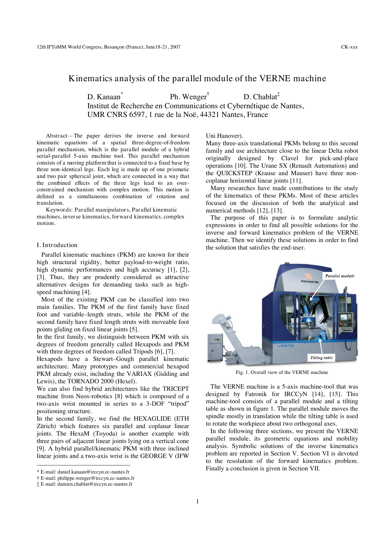
The purpose of this paper is to formulate analytic expressions in order to find all possible solutions for the inverse and forward kinematics problem of the VERNE machine. Then we identify these solutions in order to find the solution that satisfies the end-user. The VERNE machine is a 5-axis machine-tool that was designed by Fatronik for IRCCyN [14], [15]. This machine-tool consists of a parallel module and a tilting table as shown in figure 1. The parallel module moves the spindle mostly in translation while the tilting table is used to rotate the workpiece about two orthogonal axes.
In the following three sections, we present the VERNE parallel module, its geometric equations and mobility analysis. Symbolic solutions of the inverse kinematics problem are reported in Section V. Section VI is devoted to the resolution of the forward kinematics problem. Finally a conclusion is given in Section VII. Figure 2 shows a scheme of the parallel module of the VERNE machine. The kinematic architecture can be described by a simple scheme shown in figure 3, where joints are represented by rectangles and links between those joints are represented by lines (P and S indicate prismatic and spherical joint, respectively). The moving platform is rectangular. The vertices of this platform are connected to a fixed-base plate through three legs Ι, ΙΙ and ΙΙΙ. Each leg uses pairs of rods linking a prismatic joint to the moving platform through two pair spherical joints. Legs ΙΙ and ΙΙΙ are two identical parallelograms. Leg Ι differs from the other two legs in that 11 12 11
, that is, it is not an articulated parallelograms. The movement of the moving platform is generated by the slide of three actuators along three vertical guideways. Using the Grubler formula recalled in Equation (1), it can be proved that the mobility m of the platform is equal to three:
where m denotes the mobility of the manipulator, p N is the total number of rigid bodies of the manipulator,
In order to analyse the kinematics of our parallel module, two relative coordinates are assigned as shown in figures 2. A static Cartesian frame xyz is fixed at the base of the machine tool, with the z-axis pointing downward along the vertical direction. The mobile Cartesian frame,
x y z , is attached to the moving platform at point P and remains parallel to xyz.
In any constrained mechanical system, joints connecting bodies restrict their relative motion and impose constraints on the generalized coordinates, geometric constraints are then formulated as algebraic expressions involving generalized coordinates. Using the parameters defined in figure 4, the constraint equations of the parallel manipulator are expressed as:
where ij A (respectively ij B ) is the center of spherical joint number j on the prismatic joint number i (respectively on the moving platform side), i = 1..3, j = 1..2. 3) and ( 4). This is due to the fact that 11 12
cos( ) sin( ) 0
cos( ) sin( ) 0
Leg ΙΙ is represented by a single equations (5).
The leg ІІІ, which is similar to leg
…(Full text truncated)…
This content is AI-processed based on ArXiv data.